TJ1400P-M1 switch is an enterprise grade L2/L3 device suitable for enterprises that need L2/L3 switching functionalities. The Tejas Networks TJ1400P-M1 Ethernet switches run the Enterprise version of the Tejas Network Operating System (TejNOS-EN), which provides Layer 2 and Layer 3 Switching, Routing, and Security services.
This chapter provides an overview of TJ1400P-M1 switches, list of different variants available, details the physical dimensions, and overview of the interfaces of the system. It also provides the hardware details of the Switch along with the behavior of LEDs present on the switch. The user can check the switch status by reading the LED behaviors and reset the switch or restore the switch to factory defaults.
TJ1400P-M1 switches are available in models with 8-port and 24-port built-in network ports that support RJ-45 cable and optical cable connectors.
The following are the models available for fixed 8-port switches. Table 1: 8-port switch models Switch model Description 8-port rack-mount switch models Non-PoE model TJ1400-M1-8T4S-LS 8-port 10/100/1000 BaseT RJ45 and 4xSFP AC powered extended temperature L2/CE/L3 switch PoE models TJ1400-M1-8P4S-LS 8-port 10/100/1000 BaseT RJ45 and 4xSFP AC powered extended temperature L2/CE/L3 low wattage PoE+ switch TJ1400-M1-8HP4S-LS 8-port 10/100/1000 BaseT RJ45 and 4xSFP AC powered L2/CE/L3 PoE+ switch 8-port DIN-rail mount switch models Non-PoE model TJ1400-M1-8T4S-LSv2-IT-DC-DIN 8-port 10/100/1000BaseT RJ45 and 4xSFP DC powered L2/CE/L3 DIN-Rail Industrial Grade switch PoE models TJ1400-M1-8HP4S-LSv2-IT-DC-DIN 8-port 10/100/1000BaseT RJ45 and 4xSFP DC powered L2/CE/L3 DIN-Rail Industrial Grade PoE+ switch TJ1400-M1-8UP4S-LSv2-IT-DC-DIN 8-port 10/100/1000BaseT RJ45 and 4xSFP DC powered L2/CE/L3 DIN-Rail Industrial Grade UPoE switch
3.1 Rack mount switch
Front Panel of 8-port TJ1400P-M1 switch with AC Power Supply Unit
The following figure describes the front panel components of 8-port switch. The front panel view of TJ1400P-M1 8x1 GE (electrical) + 4 SFP GE (Optical) variant, ports 1 to 8 supports 1GE (10/100/1000 Base-T) interfaces and ports 9 to 12 supports 1G uplink optical interfaces.
Figure 1: Front panel of TJ1400P-M1 AC switch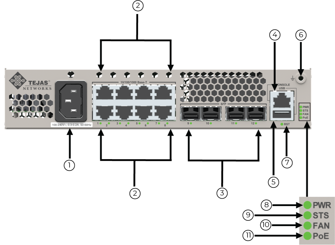
1 | AC Power connector | 7 | RST (Reset button) |
2 | Ports 1-8 of 10/100/1000 Base-T ports | 8 | PWR (Power) LED |
3 | Ports 9-12 of SFP module ports | 9 | STS (Status) LED |
4 | RJ-45 Console port | 10 | FAN LED |
5 | USB type A port | 11 | PoE LED |
6 | Ground connector | ||
The TJ1400P-M1 8-port switch front panel has the following combinations of ports:
• 8x1GE + 4xSFP AC variant non-PoE switch, ports 1 to 8 supports 1 Gigabit Electrical (10/100/1000 Base-T) interfaces, and ports 9 to 12 supports 1 Gigabit Optical uplink interfaces.
Figure 2: TJ1400P-M1 8-port non-PoE switch front panel view with fixed AC PSU
• 8xGE + 4xSFP AC variant PoE switch, ports 1 to 8 supports 1 Gigabit Electrical (10/100/1000 Base-T) interfaces, and ports 9 to 12 supports 1Gigabit Optical uplink interfaces.
Figure 3: TJ1400P-M1 8-port PoE switch front panel view with AC PSU 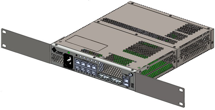
Rear panel view of TJ1400P-M1 8-port switch
The following figure shows the rear panel of TJ1400P-M1 switch.
Figure 4: TJ1400P M1 8-port switch rear panel
The following figure shows the front panel view of TJ1400P-M1 8-port switch with DC PSU DIN-rail.
Figure 5: TJ1400P-M1 8-port front view DIN-rail switch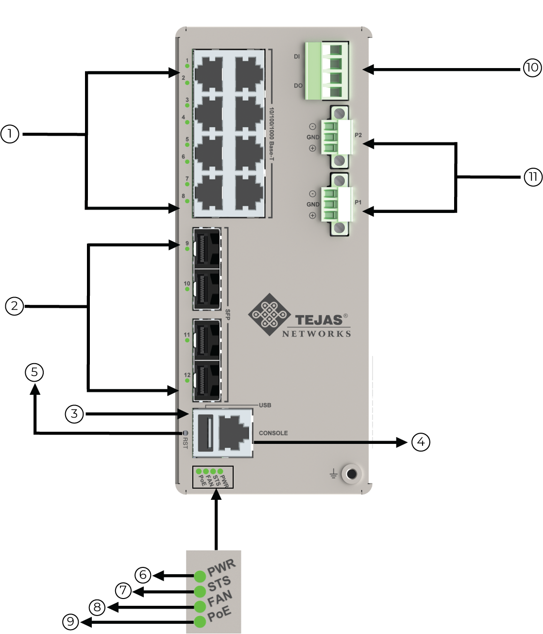
1 | Ports 1-8 of 10/100/1000 Base-T ports | 6 | PWR (Power) LED |
2 | Ports 9-12 of SFP module ports | 7 | STS (Status) LED |
3 | USB type A port | 8 | FAN LED |
4 | RJ-45 Console port | 9 | PoE LED |
5 | RST (Reset button) | 10 | Alarm connector |
11 | DPUIO | ||
Figure 6:
The following figure shows the rear panel view of TJ1400P-M1 switch with DC PSU -DIN Rail PoE and non-PoE variant.
Figure 7: TJ1400P-M1 8-port rear view DIN-rail switch
Note: The DIN-rail switch comes with DIN rail clamps and the customer can use the appropriate location depending on the installation requirements.
The following are the models available for 24-port switches: Table 2: Switch models and description for 24-port Switch model Description 24-port electrical switch fixed models Non-PoE TJ1400-M1-24TS-LSv2 24-port 10/100/1000 BaseT RJ45 and 4x1G SFP AC powered L2/CE/L3 switch TJ1400-M1-24TD-LSv2 24-port 10/100/1000 BaseT RJ45 and 4x10G SFP+ AC powered L2/CE/L3 switch PoE TJ1400-M1-24LPS-LSv2 24-port 10/100/1000 BaseT RJ45 and 4x1G SFP AC powered L2/CE/L3 low wattage PoE+ switch TJ1400-M1-24LPD-LSv2 24-port 10/100/1000 BaseT RJ45 and 4x10G SFP+ AC powered low wattage L2/CE/L3 switch TJ1400-M1-24PS-LSv2 24-port 10/100/1000 BaseT RJ45 and 4X1G SFP AC powered L2/CE/L3 PoE+ switch TJ1400-M1-24PD-LSv2 24-port 10/100/1000 BaseT RJ45 and 4x10G SFP+ AC powered L2/CE/L3 PoE+ switch 24-port optical switch fixed model TJ1400P-M1-24SD-LSv2 24-port SFP and 6xSFP+ AC and DC powered L2/CE/L3 optical switch
Front panel of a 24-port M1 switch with AC power supply unit
The following figure describes the front panel components of 24-port switch.
• 24x1GE + 4x10GE AC supply PoE/non-PoE variant, where P1 to P24 supports 1 Gigabit Electrical (10/100/100 Base-T) interfaces, P25 to P28 supports 10 Gigabit Optical (SFP+) interfaces, and stacking ports S1 and S2.
Figure 8: TJ1400P-M1 24-Port AC PSU switch
1 | Ports P1 to P24 of 10/100/1000 Base-T ports | 6 | PWR (Power) LED |
2 | Ports P25 to P28 of SFP/SFP+ Uplink ports | 7 | PoE LED |
3 | S1 and S2 Stacking ports (if stacking ports are supported) in 24-port electrical switch | 8 | FAN LED |
4 | RJ-45 console port | 9 | RST (Reset button) |
5 | USB type-A port | 10 | AC power connector |
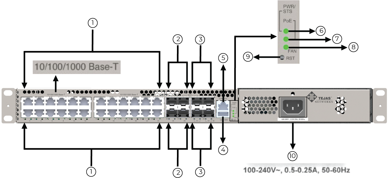
Note: If stacking ports are disabled, then the port S1 is not supported and the port S2 acts as two uplink ports with the port numbers as P29 and P30.
Front panel view of TJ1400P-M1 24-port electrical fixed variant switch
Figure 9: Front View: TJ1400P-M1 with 24 Gigabit electrical ports
Rear panel view of TJ1400P-M1 24-port electrical fixed variant switch
Figure 10: Rear View: TJ1400P-M1 with 24 Gigabit electrical ports
Front panel view of TJ1400P-M1 24-port optical fixed variant switch
The following figure describes the front panel components of 24-port switch. The front panel view of TJ1400-M1 fixed 24 SFP + 6 SFP+ variant, P1 to P24 supports 1 Gigabit optical (SFP) interfaces, P25 to P30 supports 10 Gigabit Optical (SFP+) uplink interfaces.
Figure 11: Front View: TJ1400P-M1 with 24-port Gigabit optical ports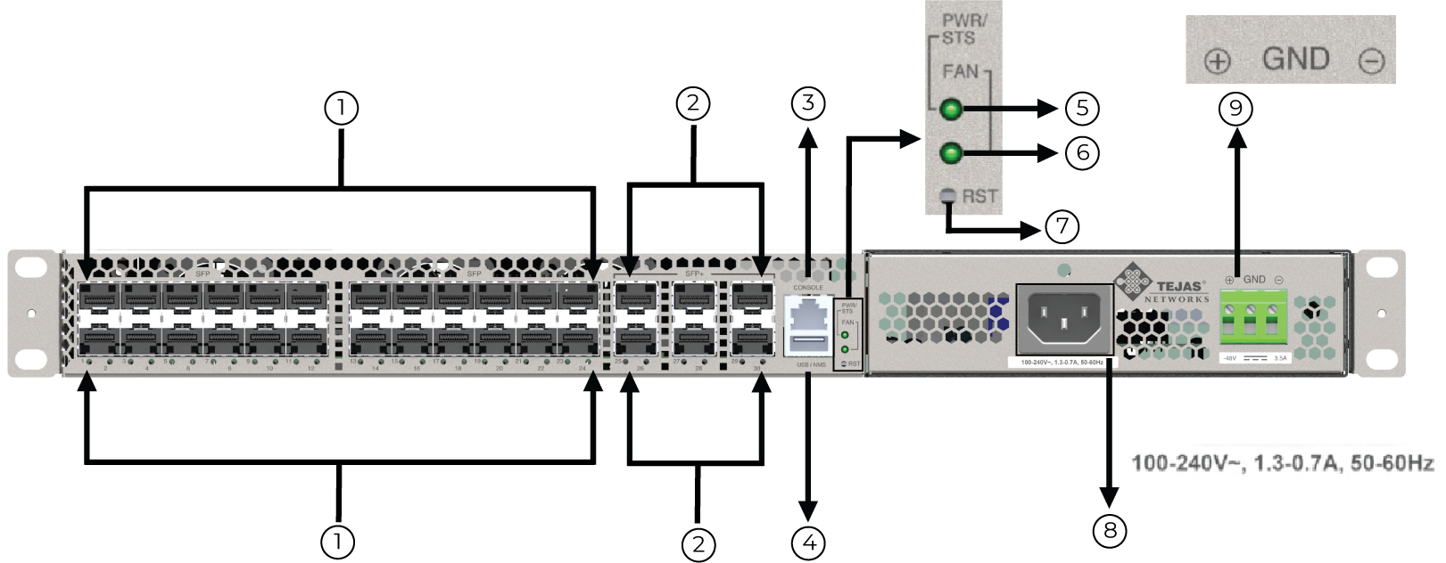
1 | P1 to P24 of optical ports | 6 | FAN LED |
2 | P25 to P30 of SFP+ uplink ports | 7 | RST (Reset button) |
3 | RJ-45 Console port | 8 | AC power connector |
4 | USB type-A port | 9 | DC power supply unit |
5 | PWR (Power) LED | ||
Note: The TJ1400P-M1 switch has three fans in its PoE model electrical variant and three fans with non-PoE model optical variant.
3.2 LED specifications
3.2.1 LED description
LEDs on the front panel of TJ1400P-M1 8-port and 24-port switch allows user to monitor and check the status of the switch. LEDs provide system and port indication.
There are two types of LEDs as follows:
• Port status LEDs: Indicates the current status of each port. User can check these LEDs to understand the port status.
• System LEDs: Indicates if the switch is powered up correctly or not.
3.2.2 Visual Indicator Details of 8-port and 24-port switch Table 3: 8-Port switch LED Specifications LED label Description LED color Significance Power Indicates the status of the PSU Green (default) Indicates presence of output voltage. Fan Indicates the status of fan Off (default) Fanless system PoE Indicates the status of current drawn by Powered Devices of PoE (for all PoE ports) Green PoE enabled, supplying power to the connected Powered Device. When current is within the limit, that is at least one power device is drawing power. Off (default) PoE is not enabled. Table 4: 24-Port switch LED Specifications LED label Description LED Color Significance Power Indicates the status of the PSU Green blinking (default) Board is powered on. Driven by hardware. Green On software initialization. Red On software crash/ reload. Status Indicates the status of switch Green Software is booted up. Red Indicates in any of the following circumstance: • Software crash • Reboot • Node hangs Fan Indicates the status of fan Off Fanless system. Green Fan is present and working. Red Fan is present and not working. PoE Indicates the status of current drawn by PD of PoE (for all PoE ports) Off (Default) If PoE is disabled. (Default behavior in SW) Green If PoE is enabled.
The following table describes the functions of and descriptions of the LED indicator. Only one LED is used to transmit and receive traffic on RJ45 and SFP ports.
LED | Color | State | Description |
Per port LED RJ45/SFP ports | Green | Admin Up | Indicates that the port obtains output voltage. |
Green and blinking | Traffic/Activity | Indicates port is transmits and receives data or traffic. | |
Off | Admin down | Indicates the port is admin down. |
3.3 Electrical RJ45 Interfaces
3.3.1 10/100/1000 Base-T ports for 8-port and 24-port switch
The ethernet traffic is received and transmitted from the 10/100/1000 Base-T interface on TJ1400P-M1 switch. The connectivity is made through RJ45 connectors and the switch contains 10/100/1000 Base-T RJ-45 ports. All RJ-45 ports support automatic, so the optimum data rate and transmission is selected automatically. The number of 10/100/1000 Base-T ports on a switch depends on the type of TJ1400P-M1 switch. The GE RJ-45 copper interface ports support 10 BASE-T, 100 BASE-Tx, and 1000 BASE-T.
The following figure shows the electrical ports on TJ1400P-M1 8-port switch.
Figure 12: 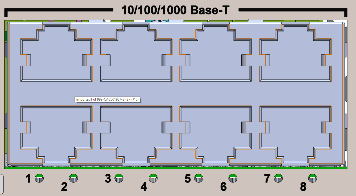 TJ1400P-M1 8-port switch 10/100/1000 Base-T ports
The following figure shows the electrical ports on TJ1400P-M1 24-port switch.
Figure 13:  TJ1400P-M1 24-port switch 10/100/1000 Base-T Ports
3.3.2 SFP and SFP+ module ports for 8-port and 24-port switch
A SFP is a hot-swappable input/output device that connects the switch to the fiber-optic network by plugging the SFP ports. The switch uses Gigabit Ethernet SFP modules. It has twenty-four 1G SFP module slots and has four 10G SFP+ module slots. These field-replaceable transceiver modules provide uplink interfaces when inserted in an SFP module slot. SFP modules have fiber-optic LC connectors. Only SFP modules are supported in the SFP slots.
The following figure shows the optical ports on TJ1400P-M1 8-port switch.
Figure 14:  TJ1400P-M1 8-port switch SFP interface
The following figure shows the optical ports on TJ1400P-M1 24-port switch. It has four SFP+ module slots as shown in the figure.
Figure 15: TJ1400P-M1 24-port electrical switch SFP+ ports
The switch provides fixed uplink ports that support 10 Gigabit optical SFP+ modules. It has four 10G SFP+ module slots. These field-replaceable transceiver modules provide uplink interfaces when inserted in an SFP+ module slot. SFP+ modules have fiber-optic LC connectors. Only SFP+ modules are supported in the SFP+ slots.
The following figure shows the optical ports on TJ1400P-M1 24-port switch. It has six SFP+ module slots as shown in the figure.
Figure 16: TJ1400P-M1 24-port optical switch SFP+ ports
3.3.3 Console and USB Port
The console port is an RJ-45 serial data terminal equipment (DTE) port that can be used for either local or remote administration.
Figure 17: TJ1400P-M1 8-port and 24-port Console and USB ports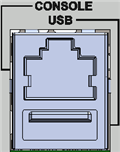
3.3.4 Ground terminal
TJ1400P-M1 switch is provided with a local safety ground terminal on the switch.
Figure 18:  TJ1400P-M1 switch 8-port and 24-port Ground terminal
The following table details the specifications of the rack mount TJ1400P-M1 8-port switch.
Table 6:
Type | Parameter | Value | |
|---|---|---|---|
Installation rack | Installation rack type | 19" (inch) | |
Switch installation rack height | 1 Rack Unit (RU) | ||
Air flow direction in the switch | Natural convection | ||
Mechanical specification | Height | 44mm | |
Width | Without mount angles | 220mm | |
With mount angles | 482mm | ||
Depth | Without PoE | 155mm | |
With PoE | 270mm | ||
The following table details the specifications of the DIN-rail TJ1400P-M1 8-port switch. Table 7: DIN-rail TJ1400P-M1 8-port switch system specifications Type Parameter Value Installation rack Installation rack type DIN-rail Switch installation rack height Air flow direction in the switch Natural convection Mechanical specification Height 70mm Width (PoE/Non-PoE) 166mm Depth (PoE/Non-PoE) Without mounting clip 160mm With mounting clip 154mm
The following table details the specifications of the TJ1400P-M1 24-port switch.
Table 8: Type Parameter Value Installation rack Installation rack type 19" (inch) Chassis installation rack height 1 Rack Unit (RU) Air flow direction in the chassis Without fan: Natural convection With fan: Enters from front to rear Mechanical specification Height 44mm Width Without mount angles 443mm With mount angles 482mm Depth 471mm