![]()
![]()
![]()
|
|
|
|
This section covers the features and description of the OAM (Operation, Administration and Management) interfaces on OAM card supported in TJ1600-11. The OAM interface provides static user interfaces and visual indications for managing operations, administration and maintenance of the system.This card is supported in slot 14 of the TJ1600-11 system.
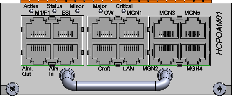
The HCPOAM01 card provides static user interfaces for configuration and visual indications. HCPOAM01 card has the following functional features:
Power specifications
TJ1600-11 HCPOAM01 - Power Specifications
Specification |
Range |
|---|---|
Input Voltage |
-48V DC |
Power consumption |
10W |
Visual indicator details
The visual indicators on the OAM include Active, Status and Alarm LEDs as per the following table:
TJ1600-11 HCPOAM01 - Status and Active LEDs indications
Card State |
Status LED |
Active LED |
|---|---|---|
Card initialization: State before the card initialize is complete on card insertion. |
Amber (Steady) |
Amber (Steady) |
Card in service: Initialization complete and card in service. |
Green (Steady) |
Green (Steady) |
Card mis-match: Node has already configured the slot with some other card. |
Amber |
Amber |
Card failed during boot up. |
Red |
Amber |
Card failed while in-service. |
Red |
Green |
Improper jack-in of the card. |
Green (Blinking) |
Green (Blinking) |
Hard Reset: All devices reset. Goes to initializing state next. |
Amber |
Amber |
Soft Reset: Software is restarted, devices are reinitialized with provisioning. Goes to initializing state next. |
Green |
Green |
There are three alarm visual indications on the faceplate of HCPOAM01 card:
TJ1600-11 HCPOAM01 - Alarm LEDs indications
LED |
Color |
LED Status |
|---|---|---|
Critical LED |
Red |
Critical alarm detected by node. |
Off |
Default State. No Critical alarm detected. |
|
Major LED |
Red |
Major alarm detected by the node. |
Off |
Default State. No Major alarm detected. |
|
Minor LED |
Amber |
Minor alarm detected by the node. |
Off |
Default State. No Minor alarm detected. |
Backplane interface
HCPOAM01 card connects to the backplane and receives the -48V DC input through the backplane.
ESI interface
The HCPOAM01 card provides ESI clock/ data interface on a RJ-45 connector.
LAN interface
The LAN Interface provides a CSMA/CD based LAN transceiver of an Ethernet link. This is available as an RJ-45 connector. The Ethernet address is available in the non-volatile memory on the OAM card.
The LAN interface physical layer is completely implemented in hardware. The physical layer device provides clock recovery, bit timing, equalization and a ‘Jabber’ circuit. The Media Access Control (MAC) function is implemented in software available as part of the microcontroller. ‘Jabber’ circuitry ensures that the transmitter does not hold up the interface for more than a full frame of data.
Two LEDs are used to indicate link status of the connector. The LAN interface is associated with two LEDs, Green and Amber.
LED status and their significance - HCPOAM01
Card State |
Green LED Status |
Amber LED Status |
|---|---|---|
Link speed 10 Mbps |
- |
- |
Link speed 100 Mbps |
- |
On |
NMS port up |
On |
- |
Receiver Activity |
Blink on packet received |
- |
Craft interface
The Local Craft terminal is an additional LAN interface. The craft is provided through a RJ-45 connector. The additional LAN interface runs a DHCP server and the port has a fixed IP address 192.168.1.1, which cannot be changed. Hence, if there is any problem with the local LAN network, the LAN port is always available for a telnet session or accessing the WUI.
External alarms interface
The OAM card provides seven external alarm inputs and four external alarm outputs.
MGN interface
HCPOAM01 provides five MGN (Management) interfaces.
MGN1 and MGN2 interfaces are used for Multi Shelf connection. The MGN1 and MGN2 on Master (Main) chassis can be connected to two other Slave (subtending) chassis using two RJ-45 cables. The Slave chassis in turn can connect to other slave chassis thus supporting a Linear or Ring form of Multi Shelf arrangement.
MGN3, MGN4, and MGN5 interfaces are used for External Management Interface Configuration from the node WUI. Among these three, any port can be used for connecting the node to a third party amplifier such as high power OFA card.