6 DWDM
This chapter covers the prominent DWDM protection features, APC, and Amplifiers supported on TJ1600 product family.
6.1 DWDM protections
This protection uses the dual fed and selective receiving function of the optical layer Lambda (wavelength) cross-connections. The protection switching is triggered by defects detected at the OPM for individual or at the amplifier for multiplexed channels. OPM is mandatory for Lambda protection.
6.1.2 FPU protection
The FPU is used for optical layer protections and the protection switching is based on the received power. In the Tx side, the optical power is split into 50% on both work and protect. In the Rx side, there is a switch which is selective receive. This supports only unidirectional switching. FPU is used in following types of protections:
• 1+1 Intra channel protection (OCH)
• 1+1 Intra board protection (OMS)
• 1+1 Optical line protection (OTS)
Note: FPU switching is based on OTUk/ODUk alarms.
6.1.2.1 1+1 Intra channel protection (OCH)
Line-side protection protects the OCH service on single channels and optical-layer boards such as multiplexer/demultiplexer boards and boards at OLA sites.
Figure 7: 1+1 Intra channel protection (OCH).jpg)
6.1.2.2 1+1 Intra board protection (OMS)
This protects the fibers and amplifier cards between two add/drop sites.
Figure 8: Intra board protection (OMS).jpg)
6.1.2.3 1+1 Optical line protection (OTS)
This protects the fibers between two adjacent sites.
Figure 9: 1+1 Optical line protection (OTS).jpg)
6.2 APC/APB
Optical power control maintains optical transmission performance by controlling the inconsistent power across DWDM channels. The VOAs perform the channel power balancing. By enabling Automatic power balancing, the power can be controlled automatically or manually in these channels.
Power inconsistency in channels can be because of the following:
• Variations of output power between transceivers.
• Wavelength dependent Insertion loss variations of DWDM components.
• Gain variations and gain tilt in optical amplifiers.
The following figure shows the power variations in WSS after configuring Optical power control:
Figure 10: Power balanced output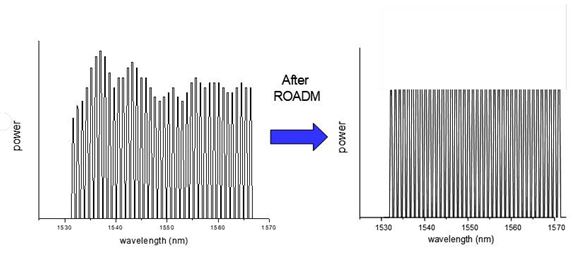
Optical Power control is achieved by following:
6.2.1 APC with VOA
OPM card uses the node logic to establish control loop between the VOA card and Monitor port of amplifier and power balance the individual channels at the amplifier output.
Figure 11: APC with VOA
NOTE: Port connect is mandatory between VOA port and add/drop port of the Mux/Demux for APC with VOA.
6.2.2 APC with WSS
OPM card uses the node logic to establish control loop between the WSS and Monitor port of amplifier and power balance the individual channels at the amplifier output.
Figure 12: APC with WSS
6.2.3 APC with CFP
Attenuation control for APC regulation is with CFP Tx power on line card. When channel power balancing required and do not have WSS or VOA card, then we can adjust CFP Tx power automatically to balance channel power. This feature is only applicable when both line card and DWDM cards are in same node.
Figure 13: APC with CFP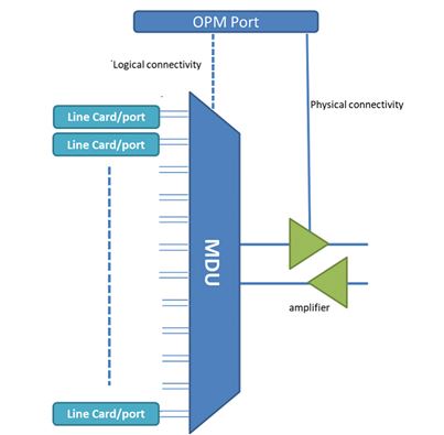
NOTE: Port connect is mandatory between line port and add/drop port of the Mux/Demux for APC with CFP.
6.3 Amplifiers
Amplifiers are the last active component in the DWDM system on the transmit side. On the receive side, the preamplifier is the first active component. The TJ1600 product family uses following amplifiers:
• EDFA
• Raman amplifier
• AGC
• APC
• APC
• APS
• APR
6.3.1 EDFA
An Erbium-Doped Fiber Amplifier (EDFA) are the type of amplifiers used. It consists of a length of silica fiber doped with erbium. This fiber is pumped using a pump signal from a laser, typically at a wavelength of 980 nm or 1480 nm. In order to combine the output of the pump laser with the input signal, the doped fiber is preceded by a wavelength-selective coupler. At the output, another wavelength-selective coupler is used to separate the amplified signal from any remaining pump signal power. An isolator is used at the input and/or output of any amplifier to prevent reflections into the amplifier.
Figure 14: EDFA amplifier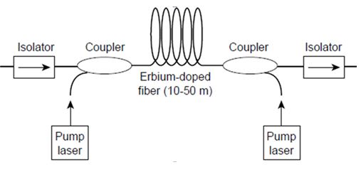
6.3.2 Raman amplifier
The Raman amplifier is an optical amplifier based on Raman amplification. This consists of dual pump around 1450nm with ~450 mW optical power such that when used in single mode fiber, a typical gain of ~ 10dB in counter propagating mode can be achieved with very low effective noise figure. This enables longer reach spans for high loss networks.
Figure 15: Raman amplifier
Raman amplifier can be used in following two ways:
6.3.2.1 Backward pump Raman amplifier
Figure 16: Backward pump Raman amplifier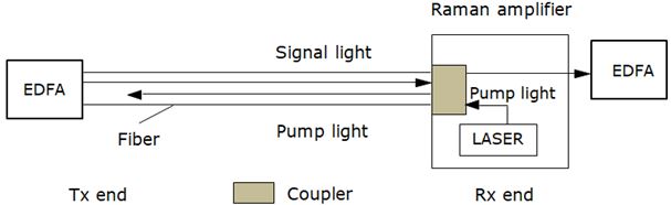
6.3.2.2 Forward pump Raman amplifier
Figure 17: Forward pump Raman amplifier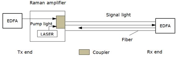
6.3.3 AGC
In this mode, gain of the amplifier can be controlled. Automatically adjusts the gain of the amplifier to compensate the span loss.
6.3.4 APC
In this mode, power of the amplifier can be controlled. Automatically adjusts the power of the amplifier to maintain constant output power.
6.3.5 APS
Due to the potential safety hazard that is posed by the high power optical outputs, the system supports APS mechanism to protect against the risk of direct human exposure to high-powered lasers. The APS mechanism acts to detect a fiber disconnection or fiber cuts along the span, and upon doing so, causes the shutdown on the same amplifier output port.
6.3.6 APR
APR reduces the output power level on open line out ports to a safe eye level. If either line output port on the system is open or becomes disconnected, the output power of the port is attenuated to bring it to safe level, if it is not already at safe level. On APR enabled port, when there is a loss of input power on coupled amplifier port, laser shuts down and stop transmitting power at APR enabled port.
6.4 C-D-C-G
This section introduces Colorless-Directionless-Contentionless-Gridless (CDCG) functions.
6.4.1 Colorless functions
Colorless functionality enables any wavelength to be added/dropped on any port. Operators can remotely reconfigure wavelengths without site visits.
Figure 18: Colorless
6.4.2 Directionless functions
Directionless functionality allows any wavelength to be routed to any direction by software without any physical changes.
Figure 19: Directionless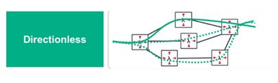
6.4.3 Contentionless functions
Contentionless ROADMs eliminate wavelength blocking so that operators can add or drop the same wavelength at the same add/drop structure. Together the capabilities of Colorless, Directionless, and Contentionless (CDC) are what provide ultimate flexibility at the optical layer required for a fully agile photonic architecture.
Figure 20: Contentionless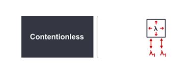
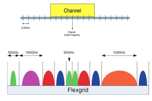
6.4.4 Gridless
Flex-grid offers service providers the ability to define individual spectral widths for each wavelength.The channels spectral width must be a multiple of 6.25GHz.
This is commonly referred to as "n x 6.25 GHz".
For example, a wavelength can be assigned a spectral width of:
• 37.5 GHz = 6 x 6.25 GHz
• 50 GHz = 8 x 6.25 GHz
• 75.0 GHz = 12 x 6.25 GHz
Figure 21: Gridless