12 Connect Ethernet ports on cards
This chapter covers procedures for connecting cables to Ethernet ports on cards supported in TJ1600 product family.
12.1 Connect ports on CEF-5 card
This section describes connecting 10GigE and GigE ports on CEF-5 card.
This topic details procedures for connecting 10GigE and GigE interfaces on CEF-5 card in TJ1600-11 chassis.
12.1.1.1 Connect 10 Gbps optical interfaces
Before making interface connections, ensure that proper pluggable module has been inserted on to the interface. To connect 10 Gbps optical interfaces, perform the following steps:
1. Identify and label the LC connector cables.
2. Connect the LC connector cable securely to the interface on the card.
3. Route the cables through the cable routers securely along the left side or right side of the rack.
The following figure shows 10 Gbps optical interfaces on CEF-5 card:
Figure 184: .jpg) 10G Connections (CEF-5 Card)
10G Connections (CEF-5 Card)
The following figure shows 10 Gbps optical interfaces on HCPSLine31 card:
Figure 185: .jpg) 10G Connections (Line-31 Card)
10G Connections (Line-31 Card)
NOTE: When a CEF-5 card is jacked-in without any license present on the node, the default port configuration supported is 2x10G. A license is required to be generated during node commissioning to enable other 10G ports on CEF-5 card. For procedure to enable this license feature, refer TJ1600 Product Family User Interface Guide.
12.1.1.2 Connect 1 Gbps optical and electrical interfaces
Before making port connection, make sure that proper SFP pluggable has been inserted on to the port.
Perform the following steps to connect LC connector cable to the 1000BASE-X optical port:
1. Identify and label the LC connector cable.
2. Connect the cable to the LC connector securely.
3. Route the cable through the cable routers securely along the left side or right side of the rack.
Perform the following steps to connect RJ-45 connector cable to the 10/100/1000 BASE-TX electrical port:
1. Identify and label the RJ-45 connector cable.
2. Connect the cable to RJ-45 connector.
3. Route the cable through the cable routers securely along the left side or right side of the rack.
The following figure shows 1000BASE-X Optical and 10/100/1000 BASE-TX Electrical ports on CEF-5 card:
Figure 186: .jpg) 1G Ports (CEF5 Card)
1G Ports (CEF5 Card)
This topic details procedures for connecting 10GigE and GigE interfaces on CEF-5 card on TJ1600-6 chassis.
12.1.2.1 Connect 10 Gbps optical interfaces
CEF-5 card supports 4x10G LAN over XFP interfaces on ports P1 to P4 and 4x10G LAN over SFP+ on ports P13 to P16.
Perform the steps given below for connecting cables to the 10 Gbps optical interfaces on CEF-5 card.
1. Identify and label the LC connector cables.
2. Identify the chassis slot with CEF-5 card and the port on the card where the cable has to be connected. Ensure that appropriate XFP/SFP+ module is inserted into that port.
3. Connect the cable to the LC connector securely. Ensure that the retention slide operates to hold the connector in place.
4. Route the cables through the cable router/guide securely along the left side or right side of the rack.
The following figure shows 10Gbps optical interfaces on CEF5 card:
Figure 187:  10Gbps optical interfaces on CEF5 card
The following figure shows 10Gbps optical interfaces on HCPSLine31 card:
Figure 188:  10Gbps optical interfaces on HCPSLine31 card
NOTE: When a CEF5 card is jacked-in without any license present on the node, the default port configuration supported is 2x10G. A license is required to be generated during node commissioning to enable other 10G ports on CEF5 card. To enable this license feature, refer the document TJ1600 Product Family User Interface Guide.
12.1.2.2 Connect 1 Gbps optical and Electrical Interfaces
CEF-5 card supports 8x1000BASE-X over SFP interfaces on ports P5 to P12 and 4x10/100/1000BASE-TX over RJ45 interfaces on ports P17 to P20.
Perform the following steps for connecting cables to the optical interfaces on CEF-5 card:
1. Identify and label the LC connector cables.
2. Identify the chassis slot with CEF-5 card and the interfaces on the card where the cables have to be connected. Ensure that appropriate SFP module is inserted into the optical ports.
3. Connect the cable to the LC connector securely.
4. Route the cables through the cable router/guide securely along the left side or right side of the rack. Ensure that the retention slide operates to hold the connector in place.
The following figure shows 1000BASE-X optical interface connections in CEF-5 card:
Figure 189: 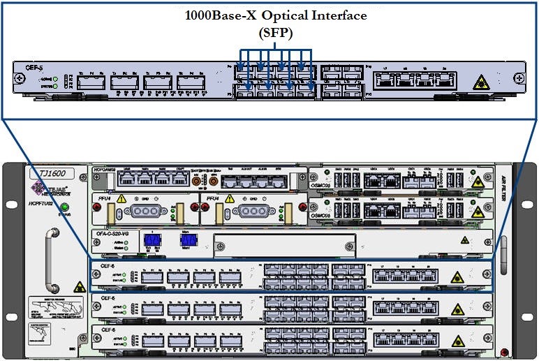 Connecting CEF-5 Card Interface- 1000BASE-X
Perform the following steps for connecting cables to the electrical interfaces on CEF-5 card:
1. Identify and label the cables.
2. Identify the chassis slot with CEF-5 card and the interfaces on the card where the cables have to be connected.
3. Connect the cable to the RJ-45 connector securely.
4. Route the cables through the cable router/guide securely along the left side or right side of the rack.
Following figure shows 4x10/100/1000BASE-TX electrical interface connections in CEF-5 card:
Figure 190:  Connecting CEF-5 Card Interface- 10/100/1000BASE-TX
12.2 Connect Ethernet ports on optical tributary cards
This section describes connecting cables to 100GigE, 10GigE ports and GigE ports on tributary cards in TJ1600-6 and TJ1600-2 chassis.
This section describes connecting Ethernet ports on the following cards in TJ1600-11 chassis:
• 100GE ports on HCPSLine12, HCPSLine22, HCPSLine24, HCPSLine27 and HCPSLine28 cards.
• 10GE ports on HCPSLine01, HCPSLine03, HCPSLine08, HCPSLine12, HCPSLine22, HCPSLine25, HCPSLine26 and HCPSLine27 cards.
• 1GE port on HCPULine01 and HCPSLine08 cards.
• 40GE port on HCPSLine12 card.
12.2.1.1 Connect 100 Gbps Optical Ports
The traffic is received and transmitted from the TJ1600 through 100GE port available on HCPSLine12, HCPSLine22, HCPSLine24, HCPSLine27 and HCPSLine28 cards. Before making port connection, ensure that proper CFP pluggable has been inserted on to the port and the screws on CFP are tightened that are provided on CFP.
Perform the following steps to connect LC connector cable to 100 Gbps optical port:
1. Identify and label the LC connector cable.
2. Connect the LC connector cable securely to the CFP on 100GE port.
3. Route the cable through the cable routers securely along the left side or right side of the rack.
The following figure shows 100GE port on HCPSLine12 card:
Figure 191:  100Gbps Interface Connection- HCPSLine12 Card
The following figure shows 100GE port on HCPSLine24 card:
Figure 192: .jpg) 100G Connection (HCPSLine24 Card)
100G Connection (HCPSLine24 Card)
The following figure shows 100GE port on HCPSLine27 card:
Figure 193:  100GE Interface Connection- HCPSLine27 Card
The following figure shows 100GE port on HCPSLine28 card:
Figure 194:  100G connection - HCPSLine28 card
12.2.1.2 Connect 10 Gbps Optical Ports
The traffic is received and transmitted from the TJ1600 through 10GE port available on HCPSLine01, HCPSLine03, HCPSLine08, HCPSLine12, HCPSLine22, HCPSLine25, HCPSLine26 and HCPSLine27 cards. Before making port connection, ensure that proper pluggable module has been inserted on to the port.
Perform the following steps to connect LC connector cable to 10 Gbps optical port:
1. Identify and label the LC connector cable.
2. Connect the cable to the LC connector securely.
3. Route the cable through the cable routers securely along the left side or right side of the rack.
The following figure shows 10 Gbps optical ports on HCPSLine01 card:
Figure 195: .jpg) 10G Connection (HCPSLine01 Card)
10G Connection (HCPSLine01 Card)
The following figure shows 10 Gbps optical ports on HCPSLine03 card:
Figure 196: 10 Gconnection (HCPSLine03 card)
The following figure shows 10 Gbps optical ports on HCPSLine08 card:
Figure 197: .jpg) 10G Connection (HCPSLine08 Card)
10G Connection (HCPSLine08 Card)
The following figure shows 10 Gbps optical ports on HCPSLine12 card:
Figure 198: .jpg) 10G Connection (HCPSLine12 Card)
10G Connection (HCPSLine12 Card)
The following figure shows 10 Gbps optical ports on HCPSLine22 card:
Figure 199: .jpg) 10G Connection (HCPSLine22 Card)
10G Connection (HCPSLine22 Card)
The following figure shows 10 Gbps optical ports on HCPSLine25 card:
Figure 200: .jpg) 10G Connection (HCPSLine25 Card)
10G Connection (HCPSLine25 Card)
The following figure shows 10Gbps optical ports on HCPSLine26 card:
Figure 201: 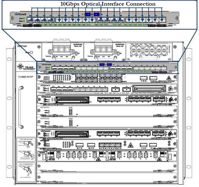 10Gbps Inteface Connection- HCPSLine26 Card
The following figure shows 10Gbps optical ports on HCPSLine27 card:
Figure 202:  10Gbps Interface Connection- HCPSLine27 Card
12.2.1.3 Connect 1 Gbps Optical Ports
The traffic is received and transmitted from the TJ1600 through 1GE port available on HCPULine01 and HCPSLine08 cards. Before making port connection, make sure that proper SFP pluggable has been inserted on to the port.
Perform the following steps to connect LC connector cable to 1000BASE-X optical port:
1. Identify and label the LC connector cable.
2. Connect the cable to the LC connector securely.
3. Route the cable through the cable routers securely along the left side or right side of the rack.
The following figure shows 1Gbps ports on HCPULine01 card:
Figure 203:  Connecting 1GE interface on HCPULine01 card
The following figure shows 1Gbps ports on HCPSLine08 card:
Figure 204: .jpg) 1Gbps Connections (HCPSLine08 Card)
1Gbps Connections (HCPSLine08 Card)
12.2.1.4 Connect 40GE Optical Port
The traffic is received and transmitted from the TJ1600 through 40GE port available on HCPSLine12 cards. Before making port connection, make sure that proper CFP pluggable has been inserted on to the port.
Perform the following steps to connect LC connector cable to 40GE optical port:
Identify and label the LC connector cable.
Connect the cable to the LC connector securely.
3. Route the cable through the cable routers securely along the left side or right side of the rack.
The following figure shows 40GE port connection on HCPSLine12 card:
Figure 205: 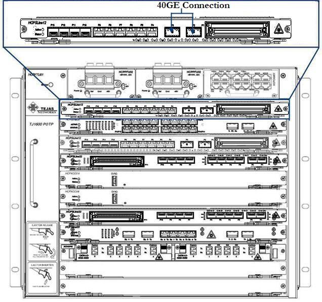 40GE Interface Connection
This section describes connecting Ethernet ports on the following cards in TJ1600-6 chassis:
• 100GE ports on HCPSLine12, HCPSLine24, HCPSLine27 and HCPSLine28 cards
• 10GigE ports on HCPSLine03, HCPSLine12, HCPSLine22, HCPSLine25, HCPSLine26 and HCPSLine27 cards.
• GigE ports on HCPSLine08 and HCPSLine22 cards
• 40GE ports on HCPSLine12 card
12.2.2.1 Connect 100 Gbps Optical Ports
The traffic is received and transmitted from the TJ1600 through 100GE port available on HCPSLine12, HCPSLine24, HCPSLine27 and HCPSLine28 cards. Before making port connection, ensure that proper CFP pluggable has been inserted on to the port and the screws on CFP are tightened that are provided on CFP.
Perform the following steps to connect LC connector cable to 100 Gbps optical port:
1. Identify and label the LC connector cable.
2. Connect the LC connector cable securely to the CFP on 100GE port.
3. Route the cable through the cable routers securely along the left side or right side of the rack.
The following figure shows 100GE port on HCPSLine12 card:
Figure 206:  100Gbps Interface Connection- HCPSLine12 Card
The following figure shows 100GE port on HCPSLine24 card:
Figure 207: 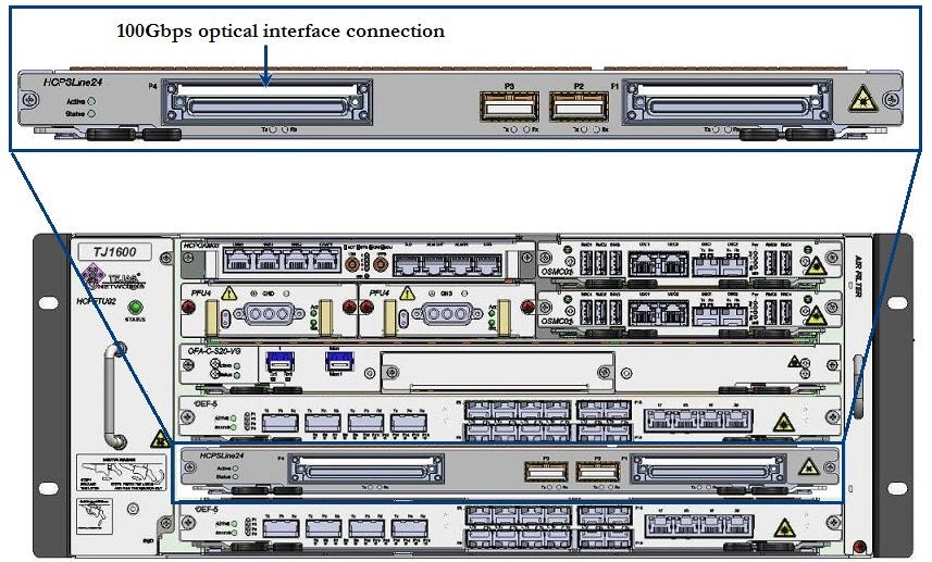 100G connection - HCPSLine24 card
The following figure shows 100GE port on HCPSLine27 card:
Figure 208:  100Gbps Interface Connection- HCPSLine27 Card
The following figure shows 100GE port on HCPSLine28 card:
Figure 209: -06.jpg) 100G connection (HCPSLine28 card)
100G connection (HCPSLine28 card)
12.2.2.2 Connect 10 Gbps Optical Ports
The traffic is received and transmitted from the TJ1600 through 10GE port available on HCPSLine03, HCPSLine12, HCPSLine22, HCPSLine25, HCPSLine26 and HCPSLine27 cards. Before making port connection, ensure that proper pluggable module has been inserted on to the port.
Perform the following steps to connect LC connector cable to 10 Gbps optical port:
1. Identify and label the LC connector cable.
2. Connect the cable to the LC connector securely.
3. Route the cable through the cable routers securely along the left side or right side of the rack.
The following figure shows 10 Gbps optical ports on HCPSLine03 card:
Figure 210: 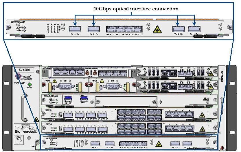 10G Connection - HCPSLine03 card
The following figure shows 10 Gbps optical ports on HCPSLine12 card:
Figure 211:  10G Connection - HCPSLine12 card
The following figure shows 10 Gbps optical ports on HCPSLine22 card:
Figure 212:  10G Connection - HCPSLine22 card
The following figure shows 10Gbps optical ports on HCPSLine25 card:
Figure 213:  10G connection - HCPSLine25 card
The following figure shows 10Gbps optical ports on HCPSLine26 card:
Figure 214:  10Gbps Interface Connection- HCPSLine26 Card
The following figure shows 10Gbps optical interface connection on HCPSLine27 card:
Figure 215:  10Gbps Interface Connection- HCPSLine27 Card
12.2.2.3 Connect 1 Gbps Optical Ports
The traffic is received and transmitted from the TJ1600 through 1GE port available on HCPSLine08 and HCPSLine22 cards. Before making port connection, make sure that proper SFP pluggable has been inserted on to the port.
Perform the following steps to connect LC connector cable to 1000BASE-X optical port:
1. Identify and label the LC connector cable.
2. Connect the cable to the LC connector securely.
3. Route the cable through the cable routers securely along the left side or right side of the rack.
The following figure shows 1Gbps ports on HCPSLine08 card:
Figure 216:  1GE connection- HCPSLine08 card
The following figure shows 1Gbps ports on HCPSLine22 card:
Figure 217: 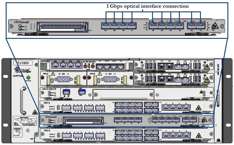 1G Connection - HCPSLine22 card
12.2.2.4 Connect 40GE Optical Port
The traffic is received and transmitted from the TJ1600 through 40GE port available on HCPSLine12 cards. Before making port connection, make sure that proper CFP pluggable has been inserted on to the port.
Perform the following steps to connect LC connector cable to 40GE optical port:
1. Identify and label the LC connector cable.
2. Connect the cable to the LC connector securely.
3. Route the cable through the cable routers securely along the left side or right side of the rack.
The following figure shows 40GE port connection on HCPSLine12 card:
Figure 218:  40GE Interface Connection- HCPSLine12 Card
This section describes connecting Ethernet ports on the following cards in TJ1600-2 chassis:
• 100GE ports on HCPSLine12, HCPSLine24, HCPSLine27 and HCPSLine28 cards
• 10GigE ports on HCPSLine03, HCPSLine12, HCPSLine22, HCPSLine25, HCPSLine26 and HCPSLine27 cards.
• GigE ports on HCPSLine08 and HCPSLine22 cards
• 40GE port on HCPSLine12 card.
12.2.3.1 Connect 100 Gbps optical ports
The traffic can be received and transmitted from TJ1600-2 system through 100GE optical ports on HCPSLine12, HCPSLine24, HCPSLine27 and HCPSLine28 card. Before making connection, ensure that proper pluggable module is inserted on to the port. The connectivity is made through LC connectors.
Perform the following steps for connecting cable to 100 Gbps optical Ethernet port on cards:
1. Identify and label the LC connector cable.
2. Face towards front of the chassis, identify the chassis slot with the desired card and port on the card where the cable has to be connected.
3. Connect the LC connector cable to the 100GE port. Ensure that retention slide operates to hold the connector in place.
4. Route the cable securely through the cable routers along left side or right side of the rack depending on the position of card.
The following figure shows 100Gbps optical port on HCPSLine12 card:
Figure 219:  100Gbps Interface Connection- HCPSLine12 Card
The following figure shows 100Gbps optical ports on HCPSLine24 card:
Figure 220: 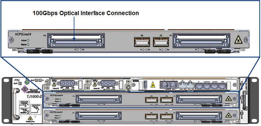 100G connection - HCPSLine24 card
The following figure shows 100Gbps optical ports on HCPSLine27 card:
Figure 221:  100Gbps Interface Connection- HCPSLine27 Card
The following figure shows 100 Gbps optical ports on HCPSLine28 card:
Figure 222:  100Gbps Ports- HCPSLine28 Card
12.2.3.2 Connect 10 Gbps optical ports
The traffic is received and transmitted from the TJ1600 through 10GE port available on HCPSLine03, HCPSLine12, HCPSLine22, HCPSLine25, HCPSLine26 and HCPSLine27 card. Before making port connection, ensure that proper pluggable module has been inserted on to the port.
Perform the following steps to connect LC connector cable to 10 Gbps optical port:
1. Identify and label the LC connector cable.
2. Connect the cable to the LC connector securely.
3. Route the cable through the cable routers securely along the left side or right side of the rack.
The following figure shows 10 Gbps optical ports on HCPSLine03 card:
Figure 223:  10G connection - HCPSLine03 card
The following figure shows 10 Gbps optical ports on HCPSLine12 card:
Figure 224:  10G Connection- HCPSLine12 card
The following figure shows 10 Gbps optical ports on HCPSLine22 card:
Figure 225: 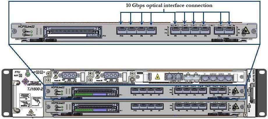 10G Connection- HCPSLine22 card
The following figure shows 10 Gbps optical ports on HCPSLine25 card:
Figure 226:  10G connection - HCPSLine25 card
The following figure shows 10Gbps ports on HCPSLine26 card:
Figure 227: 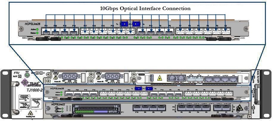 10Gbps Interface Connection- HCPSLine26 Card
The following figure shows 10Gbps ports on HCPSLine27 card:
Figure 228:  10Gbps Interface Connection- HCPSLine27 Card
12.2.3.3 Connect 1 Gbps optical ports
The traffic is received and transmitted from the TJ1600 through 1GE ports P3 to P18 available on HCPSLine08 card and 1GE ports P1 to P10 on HCPSLine22 card. Before making port connection, ensure that proper SFP pluggable has been inserted on to the port.
Perform the following steps to connect LC connector cable to 1000BASE-X optical port:
1. Identify and label the LC connector cable.
2. Connect the cable to the LC connector securely.
3. Route the cable through the cable routers securely along the left side or right side of the rack.
The following figure shows 1 Gbps optical ports on HCPSLine08 card:
Figure 229:  1G Connection- HCPSLine08 card
The following figure shows 1 Gbps optical ports on HCPSLine22 card:
Figure 230:  1G Connection- HCPSLine22 card
12.2.3.4 Connect 40GE Optical Port
The traffic is received and transmitted from the TJ1600 through 40GE port available on HCPSLine12 cards. Before making port connection, make sure that proper CFP pluggable has been inserted on to the port.
Perform the following steps to connect LC connector cable to 40GE optical port:
1. Identify and label the LC connector cable.
2. Connect the cable to the LC connector securely.
3. Route the cable through the cable routers securely along the left side or right side of the rack.
The following figure shows 40GE port connection on HCPSLine12 card:
Figure 231:  40GE Interface Connection