14 Connect ports on DWDM cards
This chapter covers procedures for installing optical adapter cards and connecting ports on DWDM cards/units supported in TJ1600 product family.
 RISK OF EYE INJURY: Avoid direct exposure to laser beam or fiber as the invisible light can blind the person. Keep all unused optical connectors capped.
This section covers the procedure for installing standalone units such as high power Optical Fiber Amplifier (OFA), Power Splitter and Combiner Module (PSCM), Multiplexer and Demultiplexer Unit (MDU40), and TJ1600-2 passive unit.
In addition to the standard installer tool kit, following tools and equipments are required for the unit installation and cabling:
• Phillips screwdriver: To install the unit into the rack
• Four M6 mounting screws and four cage nuts
• Optical patch cords
• Cable ties
Rack-mounting the unit
Perform the following steps to install a standalone unit into the rack:
1. Depending on the access requirements, decide which side you want to use as the front side in the rack. For better cable management, ensure that the side chosen for the unit is same as that of the node in the rack.
2. Determine the positioning of the unit in the rack and the rack holes to be used for mounting. Ensure that 1RU space is available in the rack.
NOTE: TJ1600-2 passive unit requires 1.5RU height.
3. Do the suitable step of the following:
— If the rack holes are un-threaded but have bolt attached on rear side of the hole, then directly go to step 4.
— If the rack holes are square and un-threaded, attach four cage nuts over the holes in the rack post as shown in the following figure. Two cage nuts on rear side of the holes on each rack post.
Figure 270:  Install the cage nut on the rack post
4. Move the unit to the desired rack position.
5. Align the mounting holes (left and right) on front panel of the unit with mounting holes in the rack.
6. Install four M6 screws (two on each rack post) through the holes on front panel of unit, rack post, and into the cage nuts to secure the unit to the rack post.
For example, following figure shows the installation of the MDU40 unit to the rack:
Figure 271:  Installation of MDU40 unit on rack
14.2 Install the optical adapter card
Optical adapter card HCPADP01 is used to split a slot in TJ1600 chassis to 2/3rd + 1/3rd slots and HCPADP02 is used to split a slot in TJ1600 chassis to 1/2 + 1/2 slots. The divided slots have backplane support to install the following cards:
2/3RD SLOT
• Multiplexer and Demultiplexer Unit (MDU8)
• FPU01 with FPUADP01 adapter card
1/3RD SLOT
• FPU01
1/2 SLOT
• OADM1
• OADM4
• (Optical Power Monitoring) OPM
• Variable Optical Attenuator (VOA)
• Optical Time Domain Reflectometer (OTDR)
• Optical Time Domain Reflectometer Filter (OTDRF)
The following figure shows the installed adapter card on the chassis:
Figure 272:  HCPADP01 with MDU-8 card
The following figure shows the installed FPUADP01 card with FPU01 housed in 2/3rd slot of HCPADP01 on the chassis:
Figure 273: 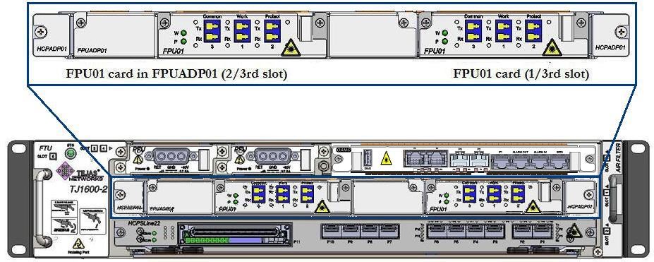 FPUADP01 with FPU01 card in 2/3rd slot of HCPADP01
The following figure shows HCPADP02 card with OADM card:
Figure 274:  HCPADP02 card with OADM cards
The slot numbers details for daughter card is as per the below mentioned table Table 10: Slot number details ADP card JI Slot No Daughter card Slot No Next Sub Slot No slot 1 30 31 32 33 34 slot 2 35 36 37 38 39 slot 3 40 41 42 43 44 slot 4 45 46 47 48 49 slot 7 60 61 62 63 64 slot 8 65 66 67 68 69 slot 9 70 71 72 73 74 slot 10 75 76 77 78 79 slot 11 80 81 82 83 84
NOTE: When the FPU inserted in ADP01 card of slot 1 then subslot#1 will be assigned with 30 and subslot#2 will be assigned with 31, which are from right to left in reference to physical card insertion.
14.3 Connect ports on OFA card
Perform the following steps to connect the amplifier ports:
1. Identify and label the LC connector cables.
2. Identify the chassis slot with OFA card and the ports on the card where the cables have to be connected.
3. Make the cable connections as follows:
— For amplifier port connection, identify the desired amplifier port on the card and connect the LC connector cable to the Tx and Rx end of that port. Ensure that the retention slide operates to hold the connector in place. Connect the other end of the cable to the Rx and Tx of an optical port on a line card.
— For monitor port connection, connect the LC connector cable to the monitor port on OFA card. Connect the other end of the cable to a power monitoring card/unit.
4. Route the cables securely through cable routers/guides along the left or right side of the rack.
The following figure shows the amplifier and monitor ports on OFA card:
Figure 275:  Optical fiber amplifier interfaces
14.4 Connect high power OFA ports
OFA-C-S26-FG is a high power OFA standalone unit. On the front panel, there are three ports namely Input, Output and Monitor. On the back panel, there are ports for Ethernet, RS232 and Monitor ports.
Perform the following steps to connect the input and monitor ports on front panel of OFA-C-S26-FG card:
1. Identify and label the LC connector cables.
2. Connect the cable to the LC connector ports and ensure that the retention slide operates to hold the connector in place.
3. Route the cables through cable routers securely along the left or right side of the rack.
Perform the following steps to connect the output port on front panel of OFA-C-S26-FG card:
1. Identify and label the E-2000 UPC connector cable.
2. Connect the cable to the E-2000 UPC connector port and ensure that the retention slide operates to hold the connector in place.
3. Route the cables through cable routers securely along the left or right side of the rack.
Perform the following steps to connect the Ethernet (LAN) and Monitor (External Alarms) ports on the back panel:
1. Identify and label the Ethernet and monitor cable.
2. Connect the cable to the RJ-45 connector port on respective ports and ensure that the retention slide operates to hold the connector in place.
3. Route the cable through cable routers securely along the left side or right side of the rack.
NOTE: The LAN interface can be connected directly to the Element Management Software (EMS) and the available NMS port on the system.
Perform the following steps to connect the RS232 interface on the back panel:
1. Identify and label the RS232 cable.
2. Connect the cable to the RS232 (RJ-45) connector port and ensure that the retention slide operates to hold the connector in place.
3. Route the cable through cable routers securely along the left or right side of the rack.
The following figure shows the ports and the corresponding connector type to be used for OFA-C-S26-FG card:
Figure 276:  Ports and connector for OFA-C-S26-FG
To configure the IP address on high power OFA card, perform the following steps:
1. Connect the RS232 port on the back panel of the OFA-S26-FG card and PC terminal with RS232 cable provided along with the system.
2. Select the port on the terminal.
3. Login and enter the login ID and password.
4. Enter the command set ipaddr<IP address>. The IP address of the amplifier and the node connected to it must be in the same subnet.
Perform the following steps to connect the MDU8-D ports:
1. Identify and label the LC connector cables.
2. Connect the cable to the LC connectors and ensure that the retention slide operates to hold the connector in place.
3. Route the cables through cable routers securely along the left or right side of the rack.
The following figure shows the ports on MDU-8-D card:
Figure 277:  Interface connection for MDU-8-D card
14.6 Connect Multiplexer and Demultiplexer Unit (MDU16-D) ports
Perform the following steps to connect the MDU16-D ports:
1. Identify and label the LC connector cables.
2. Connect the cable to the LC connectors and ensure that the retention slide operates to hold the connector in place.
3. Route the cables through cable routers securely along the left or right side of the rack.
The following figure shows the ports on MDU16-D card:
Figure 278: 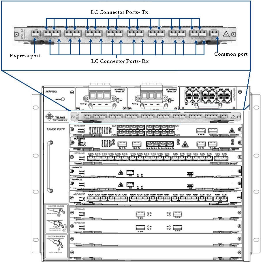 Interface connection for MDU-16-D card
14.7 Connect Multiplexer and Demultiplexer Unit (MDU40) ports
MDU40 is a 40 channel multiplexer and demultiplexer passive unit which does not require electrical power to be operational. The unit is installed in a standalone mode, requiring 1U of vertical space in a 19-inch sub-rack. It is used with TJ1600 platform for aggregating multiple channels in the optical domain.
This section covers the connections for Add/Drop ports, Monitor port, and Common port that have to be performed on a MDU40 unit.
 RISK OF EYE INJURY: Avoid direct exposure to laser beam or fiber as the invisible light can blind the person. Keep all unused optical connectors capped.
Perform the following steps to connect cables to the ports on MDU40 unit:
1. Identify and label all the LC connector cables to be used.
2. Make the cable connections as follows:
— For Add/Drop port connection, identify the desired port/channel on MDU40 unit and connect the LC connector cable to the Tx and the Rx of that port/channel. Ensure that the retention slide operates to hold the connector in place. Connect the other end of the cable to the Rx and Tx of the optical port on a line card as shown in the following figure. Note that the optical port should have a tunable SFP/XFP which is tuned to appropriate wavelength as that of port on MDU40 unit. If optical port has fixed DWDM XFP/SFP then XFP channel number must match that of MDU port.
— For Monitor port connection, connect the LC connector cable to the Mux/Demux end of the Monitor port on MDU40 unit. Connect the other end of the cable to a power monitoring card/unit as shown in the following figure.
— For Common port connection, connect the LC connector cable to the Tx and the Rx of Common port on MDU40 unit. Ensure that the retention slide operates to hold the connector in place. Connect the other end of the cable to the Rx and Tx of a Common port on another Multiplexer/demultiplexer unit as shown in the following figure:
Figure 279:  Port Connectivity Diagram for MDU-40E-C-100G Unit
3. While routing the cables, route through cable guides/routers securely along the left side or right side of the rack for better cable management.
14.8 Connect Colourless Multiplexer and Demultiplexer Unit (CLMDU) ports
Perform the following steps to connect the cables to the ports on MDU-16CL-C-50G card:
1. Identify and label the LC connector cables.
2. Connect the cable to the LC connectors and ensure that the retention slide operates to hold the connector in place.
3. Route the cables through cable routers securely along the left side or right side of the rack.
The following figure shows the ports on MDU-16CL-C-50G card:
Figure 280:  Connecting Interfaces- MDU-16CL-C-50G
14.9 Connect Multiplexer and Demultiplexer Unit (MDU96) ports
MDU40 is a 96 channel multiplexer and demultiplexer passive unit which does not require electrical power to be operational. The unit is installed in a standalone mode, requiring 1U of vertical space in a 19-inch sub-rack. It is used with TJ1600 platform for aggregating multiple channels in the optical domain.
This section covers the connections for Add/Drop ports, Monitor port, and Common port that have to be performed on a MDU-96-C-50G unit.
 RISK OF EYE INJURY: Avoid direct exposure to laser beam or fiber as the invisible light can blind the person. Keep all unused optical connectors capped.
Perform the following steps to connect cables to the ports on MDU96 unit:
1. Identify and label all the LC connector cables to be used.
2. Make the cable connections as follows:
— For Add/Drop port connection, identify the desired port/channel on MDU96 unit and connect the LC connector cable to the Tx and the Rx of that port/channel. Ensure that the retention slide operates to hold the connector in place. Connect the other end of the cable to the Rx and Tx of the optical port on a line card as shown in the following figure. Note that the optical port should have a tunable SFP/XFP which is tuned to appropriate wavelength as that of port on MDU96 unit. If optical port has fixed DWDM XFP/SFP+ then XFP channel number must match that of MDU port.
— For Monitor port connection, connect the LC connector cable to the Mux/Demux end of the Monitor port on MDU96 unit. Connect the other end of the cable to a power monitoring card/unit as shown in the following figure.
— For Common port connection, connect the LC connector cable to the Tx and the Rx of Common port on MDU96 unit. Ensure that the retention slide operates to hold the connector in place. Connect the other end of the cable to the Rx and Tx of a common port on another Multiplexer/demultiplexer unit as shown in the following figure:
Figure 281:  Interface connection on MDU-96 card
3. While routing the cables, route through cable guides/routers securely along the left side or right side of the rack for better cable management.
14.10 Connect Optical Add Drop Multiplexer (OADM) ports
Perform the following steps to connect the cables to the OADM1 and OADM4 ports:
1. Identify and label the LC connector cables.
2. Connect the cable to the LC connectors and ensure that the retention slide operates to hold the connector in place.
3. Route the cables through cable routers securely along the left or right side of the rack.
The following figure shows the ports on OADM-1 and OADM-4 cards:
Figure 282:  Interface Connection- OADM-1 and OADM-4 cards
Reconfigurable Optical Add Drop Multiplexer (ROADM) card is a reconfigurable optical add-drop multiplexer that adds the ability to remotely switch traffic from a wavelength-division multiplexing system at the wavelength layer.
Perform the following steps to connect the cables to the ports on ROADM card:
1. Identify and label the LC connector cables.
2. Connect the cable to the LC connectors and ensure that the retention slide operates to hold the connector in place.
3. Route the cables through cable routers securely along the left or right side of the rack.
The following figure shows the LC connection for ROADM-4-C-50G card:
Figure 283: 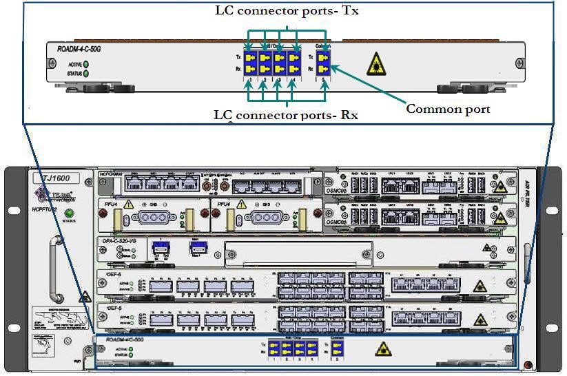 Interface connection - ROADM-4-C-50G card
The following figure shows the LC connection for ROADM-8-C-50G card:
Figure 284:  Interface connection- ROADM-8-C-50G
OPM card is used for measuring power. OPM-4-C-50G has four ports that measures optical power from either 4 monitoring input ports (such as Monitor port of OFA card).
Perform the following steps to connect the cables to the ports on OPM card:
1. Identify and label the LC connector cables.
2. Connect the cable to the LC connectors and ensure that the retention slide operates to hold the connector in place.
3. Route the cables through cable routers securely along the left or right side of the rack.
The following figure shows the ports on OPM-4-C-50G cards:
Figure 285:  Interface Connection- OPM-C-4 and OPM-C-2 Card
14.13 Connect optical PSCM ports
Perform the following steps to connect the cables to the optical ports on PSCM:
1. Identify and label the LC connector cables.
2. Connect the LC connector cable to the Tx and the Rx end of that port. Ensure that the retention slide operates to hold the connector in place.
3. Route the cables through cable routers securely along the left or right side of the rack.
The following figure shows the ports on 1x5 PSCM:
Figure 286:  Interface connection- 1x5 PSCM
Optical Fiber Monitoring (OFM) is a standalone unit. On the front panel, there are three ports namely Input, Output and Monitor.
To configure the IP address on high power OFA card, perform the following steps:
1. Connect the RS232 port on the back panel of the OFA-S26-FG card and PC terminal with RS232 cable provided along with the system.
2. On terminal, select the port.
3. Login and enter the login ID and password.
4. Enter the command set ipaddr<IP address>. The IP address of the amplifier and the node to which it will be connected must be in the same subnet.
Perform the following steps to connect the cables to the ports on Variable Optical Attenuator (VOA) card:
1. Identify and label LC connector cables.
2. Connect the LC connector cable (carrying the signal for attenuation) to the Rx end and the LC connector cable (with attenuated signal) to the Tx end of the port. Ensure that the retention slide operates to hold the connector in place.
NOTE: Connect Rx cable first and then the Tx cable.
3. Route the cables through cable routers securely along the left or right side of the rack.
The following figure shows the ports on VOA-8-C card.
Figure 287:  Interface Connection- VOA card
14.16 Connect ports on (FPU01/FPU02) card
Perform the following steps to connect the cables to the ports on Fiber Protection Unit (FPU01/FPU02) card:
1. Identify and label the LC connector cables.
2. Connect the LC connector cable to the Tx and the Rx end of that port. Ensure that the retention slide operates to hold the connector in place.
3. Route the cables through cable routers securely along the left or right side of the rack.
The following figure shows the ports on FPU01 card:
Figure 288: 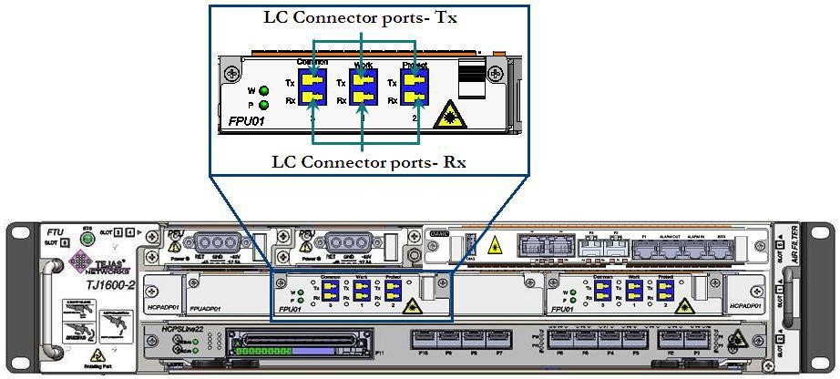 Ports on FPU01 card
Perform the following steps to connect the cables to the add drop module ports on Optical Supervisory Channel Filter (OSCF):
1. Identify and label the LC connector cables.
2. Connect the cable to the LC connectors and ensure that the retention slide operates to hold the connector in place.
3. Route the cables through cable routers securely along the left or right side of the rack.
The following figure shows the ports on OSCF-S51 card:
Figure 289:  Interface connection- OSCF-S51
Perform the following steps to connect the cables to the ports on DCM:
1. Identify and label the cables.
2. Connect the cable to the LC connectors and ensure that the retention slide operates to hold the connector in place.
3. Route the cables through cable routers securely along the left or right side of the rack.
Figure 290: 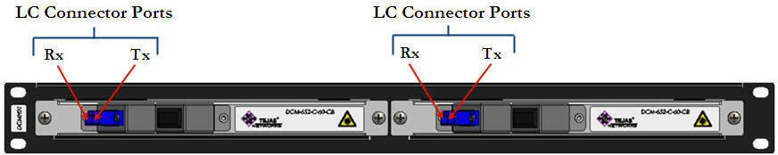 Connecting DCM interfaces
The following figure shows a diagrammatic representation of port connectivity for two DCM with a dual OSCF module and OSCF module with amplifier:
Figure 291:  Port connectivity diagram for DCM with OSCF
Perform the following steps to connect the cables to the ports on OTDR:
1. Identify and label the cables.
2. Connect the cable to the LC connectors and ensure that the retention slide operates to hold the connector in place.
3. Route the cables through cable routers securely along the left or right side of the rack.
The following figure shows the ports on OTDR-2 card
Figure 292:  Port connectivity of OTDR-2 card
The following figure shows the ports on OTDR-4 card
Figure 293:  Port connectivity of OTDR-4 card
The following figure shows the ports on OTDR-8 card
Figure 294:  Port connectivity of OTDR-8 card
Perform the following steps to connect the cables to the ports on OTDRF filter:
1. Identify and label the cables.
2. Connect the cable to the LC connectors and ensure that the retention slide operates to hold the connector in place.
3. Route the cables through cable routers securely along the left side or right side of the rack.
The following figure shows the ports on OTDRF-2 card
Figure 295:  Port connectivity of OTDRF-2 card
The following figure shows the ports on OTDRF-4 card
Figure 296:  Port connectivity of OTDRF-4card
The following figure shows the ports on OTDRF-8 card
Figure 297: Port connectivity of OTDRF-8 card