This chapter describes the procedures to be followed when cleaning and inspecting optical and fiber connectors; the SFP replacement process. It also describes the procedure to be followed during inserting and ejecting of cards and FTUs.
NOTE: Always clean the fiber-optic connectors before connecting to the transmission equipment, test equipment, patch panels, or other connectors.
20.1 Guidelines for cleaning optical fiber connectors
It is important to keep all interconnects as clean as possible. Since the single-mode fiber has a light-carrying core with diameter less than 10 micro meters, even a single microscopic speck of dust on the connector end can significantly attenuate the light traveling through the fiber. Clean connections are required for accurate and repeatable measurements. Leave the protective dust covers on the connectors when they are not in use.
Observe the following guidelines to achieve the best performance:
• Visually inspect fiber ends to locate any signs of damage.
• Use dry connections whenever possible.
• Keep connectors covered when not in use.
For more information on cleaning procedure, refer to Clean optical fiber connectors.
 CAUTION: Improper cleaning may result in high attenuation due to dirt or dust or may cause mechanical damage to the fiber end, resulting in performance degradation. While handling an optical fiber, do not exceed the minimum bed radius (35 mm). Do not over tighten the cable tie wraps while dressing the cable.
DANGER: Do not look into the end of fiber-optic connectors or into faceplate connectors of installed circuit packs. The light source used in fiber-optic devices can damage your eyes.
To inspect the fiber connectors, do the following steps:
• Verify whether the other end of the fiber is disconnected from its laser source.
• Visually inspect all fiber-optic connections before use. A minimum magnification of 200X is required for proper inspection.
Figure 353: 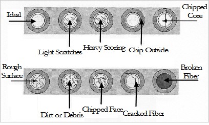 Fiber intersection
Following table provides the recommended actions for different conditions of fiber connectors. Table 69: Recommended actions for conditions of fiber connectors Fiber end-face condition Recommendation/Action Ideal No action required Light scratches Polish with 0.3 micron film Heavy scoring or scratches Repolish the face Chip outside the fiber core Repolish the face Chipped core Unacceptable; reject the connector Rough surface Repolish the face Dirt or debris Clean or repolish the surface Chipped face Unacceptable; reject the connector Cracked fiber Unacceptable; reject the connector Broken fiber Unacceptable; reject the connector
20.3 Clean optical fiber connectors
Follow the methods described in this section to clean the optical fiber connectors.
NOTE: Ensure that the power/light source is turned off before and during the cleaning of optical interfaces.
OPTICAL SAFETY: Do not stare or look directly into the optical connector output beam, as this can cause irreparable damage to your eyes and even loss of eye sight.
20.3.1 Clean with lint-free wipes
Do the following steps to clean optical fiber connectors using lint-free wipes:
1. Fold the lint-free tissue paper into a square of about 4 to 8 layers thick.
NOTE: Use only fresh and lint-free tissue papers for cleaning. Do not use normal tissue paper or anything unauthorized.
2. Apply 1 to 3 drops of fresh 99% isopropyl alcohol to one end of the tissue paper. Shake off the excess amount of alcohol.
3. Hold the fiber by the connector or cable.
4. Place the wet portion of the tissue paper on the optical surface and slowly drag it across.
NOTE: Do not retrace the cleaning path.
5. Immediately dry the optical surface with a clean, dry, and lint-free tissue paper.
6. Place the dust cap over the end of the interface to avoid re-contamination or insert the fiber for immediate use.
7. Dispose the tissue paper properly. Do not reuse tissue papers.
20.3.2 Clean connectors with swabs
Do the following steps to clean optical fiber connectors using swabs:
1. Apply 1 to 3 drops of fresh 99% isopropyl alcohol on the cleaning bud.
2. Gently insert wet cleaning bud into the connector and rotate it in a clockwise direction. Repeat the motion 2 to 3 times.
3. Immediately place the dust cap over the connector to avoid re-contamination or insert the fiber for immediate use.
4. Dispose the swab properly. Do not reuse cleaning swab.
NOTE: Always use a fresh cleaning swab (cleaning bud) for cleaning connectors.
20.3.3 Clean with dry compressed air
Do the following steps to clean optical fiber connectors using dry compressed air:
1. Hold the fiber by the connector or cable.
2. Aim a filtered, dry compressed air dust remover at a shallow angle to the fiber end face.
3. Blow the compressed air across the fiber end face from a distance of 6 to 8 inches.
4. Verify that the connector is free of dirt by inspecting the fiber optic connector with a fiberscope.
— If it is clean, cover the connector with a protective dust cover until ready to use.
This section details the insertion and the ejection procedures for the PFU in a TJ1600 node.
 CAUTION: Do not insert or remove the PFU with power cable connected to it. This could damage the unit and also create safety hazards.
 CAUTION: This equipment might have more than one power supply connection. All connection must be removed to de-energize the unit before accessing internal parts for maintenance or service.
RISK OF PERFORMANCE DEGRADATION: If the PFU is not locked properly to the chassis, it may result in intermittent failures because of poor connectivity.
 STATIC DISCHARGE DAMAGE: Static charge can damage the equipment. While handling cards for making system interconnections, wear an ESD strap to discharge the static buildup.
CAUTION: After a card is removed from the chassis, it should not be replaced into the system immediately. Wait for at least 5 seconds to ensure that unit capacitors have discharged.
TJ1600-2 system supports the PFU in slot 3 and slot 4 of the chassis in redundant state to provide input source redundancy. PFU is provided with a latch handle on front panel to aid its insertion and ejection from the chassis.
NOTE: In redundant state, the two slots allotted to the PFU must be occupied by same PFU type.
Figure 354: 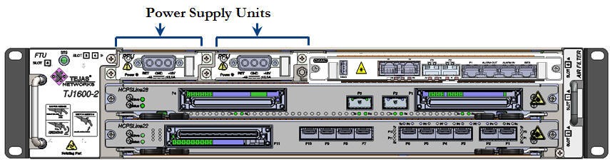 Position of PFU in TJ1600 Type-2SR chassis
Prerequisites
Before inserting or ejecting the PFU, ensure that:
• A replacement PFU is present.
• You have a precision screwdriver and a manual star screwdriver.
• You are properly grounded to the node by an ESD protective wrist strap.
• If the chassis installed on rack is at a height more than the eye level of a person, a platform of required height should be used for easy access and line of sight.
• Cables routed from left or right have sufficient slack to remove the PFU from the chassis.
Insert the PFU
Perform the following steps to insert a PFU into the chassis:
1. Face towards front of the chassis and identify the slot where the PFU has to be inserted.
2. Do one of the following:
— If the PFU is already present in the desired slot, but needs to be replaced, first remove that unit from the chassis; then go to step 3. For procedure, refer to the topic Eject the PFU.
— If the desired slot is empty, directly go to step 3.
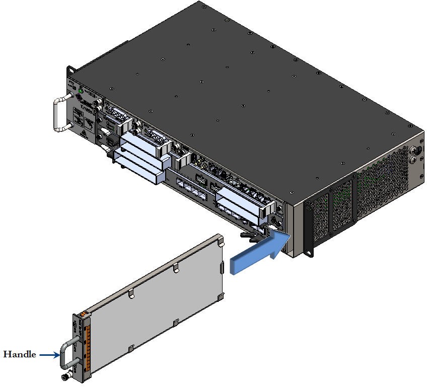
3. Hold the PFU (replacement) with proper hand support in a horizontal position against the empty slot as shown in the following figure. Slide the unit horizontally along the guide ways provided on the chassis to the point it easily goes into the chassis.
Figure 355: Sliding PFU into the chassis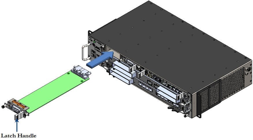
4. Hold the latch handle and gently push the PFU into the chassis to engage it to the backplane connector.
5. Secure the PFU to the chassis by tightening the captive screws present on both sides of the front panel of the unit using Phillips (PH1) star screwdriver.
Figure 356:  Tightening captive screws on PFU
Eject the PFU
Perform the following steps to eject a PFU from the chassis:
1. Face towards front of the chassis and identify the slot from where the PFU has to be removed.
2. Turn off the power supply to the PFU desired to be removed. Wait for about 15 seconds for the residual stored energy to discharge.
3. Verify that the power LED on the PFU is turned Off.
4. Loosen the two captive screws securing the power feed cable to the chassis using a precision screwdriver. The screws should be loose enough to allow the cable to be unplugged.
5. Disconnect/unplug the power feed cable by gently pulling out the cable connector from the interface.
6. Loosen the two captive screws present on both sides of the front panel of the PFU using Phillips (PH1) star screwdriver. The screws should be loose enough to allow the unit to be ejected from the chassis.
Figure 357: 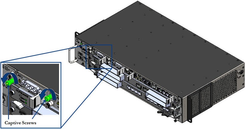 Loosening captive screws on PFU
7. Hold the latch handle and gently pull out the PFU to disengage it from the backplane connector.
8. Slide the PFU along the guide ways provided on the chassis with proper hand support till it comes out of the slot.
Figure 358: 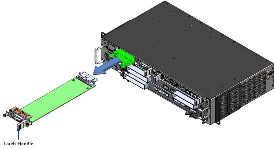 Sliding the PFU out from the chassis
This section details the insertion and the ejection procedures for the FTU in a TJ1600 node.
NOTE: Ensure that the FTU is not removed before the replacement unit is available. Also ensure that the FTU replacement procedure is completed within 30 seconds time.
 CAUTION: The fans might still be turning when you remove the fan assembly from the chassis. Keep fingers, screwdrivers, and other objects away from the openings in the fan assembly housing.
RISK OF PERFORMANCE DEGRADATION: Failure to fasten the face plate to the chassis may result in intermittent failures because of poor connectivity.
TJ1600-2 system supports the FTU in slot 6 of the chassis. FTU is located on front, towards left view of the chassis. FTU is provided with a handle on front panel that aid in its insertion and removal from the chassis.
Figure 359: 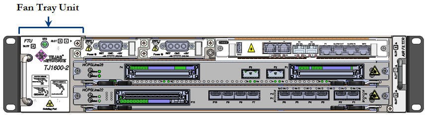 Position of FTU on TJ1600 Type-2SR chassis
FTU is designed to support redundancy mode, where each unit consists of two fans. An alarm will be raised if any of the fan fails. The system will work up to 40°C in case of single fan failure. Also, the system will work even if alarm exists on the FTU and the room temperature is below 40°C, unless the 2nd fan failure happens. It is required to change the fan if the alarm exists on the FTU.
Prerequisites
Before inserting or ejecting the FTU, ensure that:
• A replacement FTU is present.
• You have a Phillips screwdriver.
• You are properly grounded to the node by an ESD protective wrist strap.
• If the chassis installed on rack is at a height more than the eye level of a person, a platform of required height should be used for easy access and line of sight.
• Cables routed from right or left have sufficient slack to remove the FTU from the chassis.
Insert the FTU
Perform the following steps to insert a FTU into the chassis:
1. Face towards front of the chassis and identify the slot where the FTU has to be inserted.
2. Do one of the following:
— If the FTU is already present in the desired slot, but needs to be replaced, first remove that unit from the chassis; then go to step 3. For procedure, refer to the topic Eject the FTU.
— If the desired slot is empty, directly go to step 3.
3. Hold the FTU (replacement) with proper hand support in a vertical position against the empty slot as shown in the following figure. Slide the unit horizontally along the guide ways provided on the chassis to the point it easily goes into the chassis.
Figure 360: 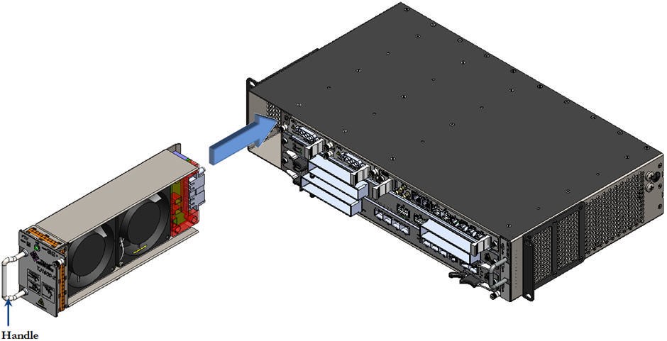 Sliding FTU into the chassis
4. Hold the handle and gently push the FTU into the chassis to engage it to the backplane connector.
5. Secure the FTU to the chassis by tightening the captive screw present on top, right side of the front panel of the unit using Phillips (PH1) star screwdriver.
Figure 361: 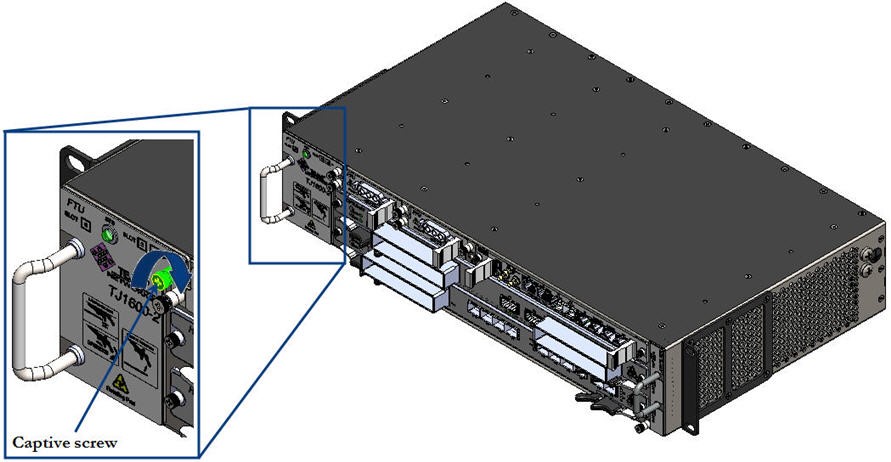 Tightening captive screw on FTU
Perform the following steps to eject a FTU from the chassis:
1. Face towards front of the chassis and identify the slot from where the FTU has to be removed.
2. Loosen the captive screw present on top, right side of the front panel of the unit using Phillips (PH1) screwdriver. The screw should be loose enough to allow the card to be removed.
Figure 362: 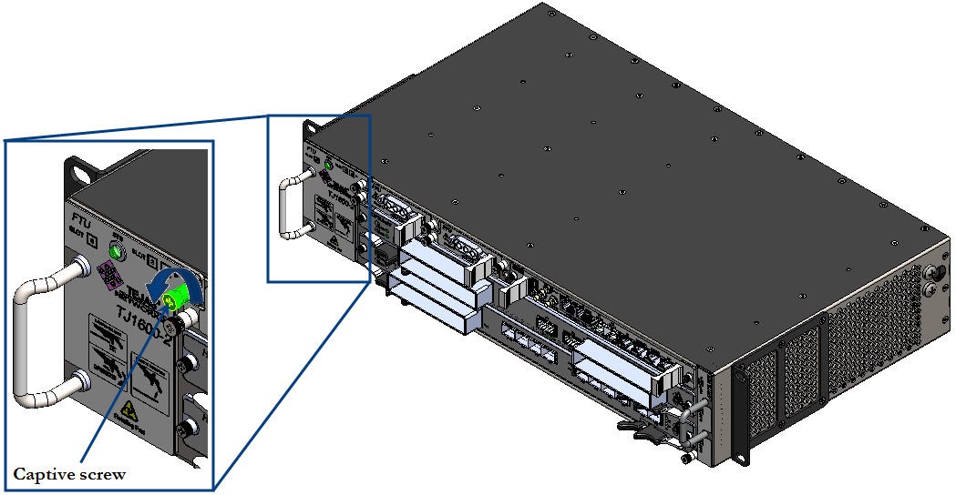 Loosening captive screw on FTU
3. Hold the handle on front panel of the FTU and gently pull out the unit to disengage it from the backplane connector.
4. Slide the FTU along the guide ways provided on the chassis with proper hand support till it comes out of the slot.
Figure 363: 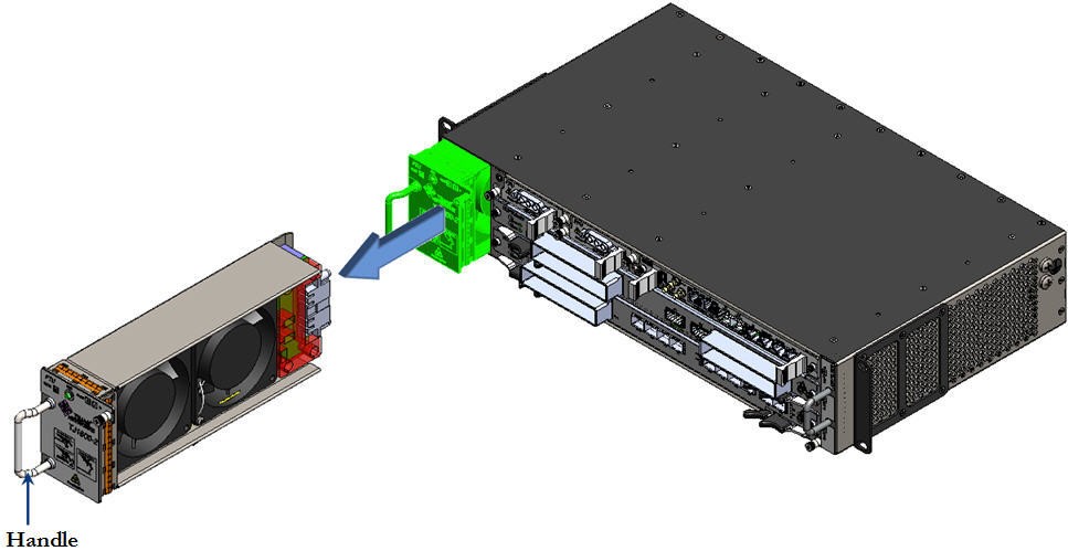 Sliding FTU out from the chassis
Insert and eject the air filter
TJ1600-2 system consists of a user-replaceable air filter that traps the dust particles from air drawn into the chassis and hence allows clean air circulation within the chassis. Air filter is a Field Replaceable Unit (FRU) located on front, towards chassis left view. It is provided with a handle on the front panel that aid in its insertion and removal from the chassis.
Figure 364: Position of air filter on TJ1600 Type-2SR chassis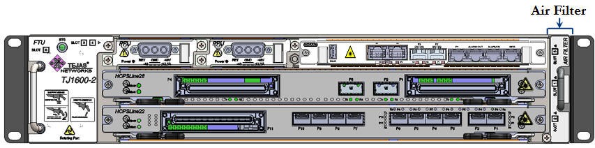
Air filters must be examined periodically. If the filter appears dirty, it can be either cleaned by vacuum or replaced. If the filter appears worn or torn, dispose of it in a responsible manner and install a replacement air filter.
NOTE: Air filter must be replaced once in every six months.
Prerequisites
Before inserting or ejecting the air filter, ensure that:
• A replacement air filter is present.
• The cables routed from left or right have sufficient slack to remove the filter.
• You have a Phillips screwdriver.
• You are properly grounded to the node by an ESD protective wrist strap.
• If the chassis installed on rack is at a height more than the eye level of a person, a platform of required height should be used for easy access and line of sight.
Insert the air filter
Perform the following steps to insert an air filter in the chassis:
1. Face towards front of the chassis and identify the slot on chassis where the air filter is desired to be inserted.
2. Hold the air filter to be installed with proper support and slide in the unit along the guide ways to the point it easily goes into the chassis. While sliding, position of the air filter should be vertical with captive screw towards down side, as shown in the following figure:
Figure 365: Sliding air filter into the chassis
3. Secure the air filter to the chassis by tightening the captive screw located on the front panel of the unit with a Phillips (PH1) screwdriver.
Figure 366: 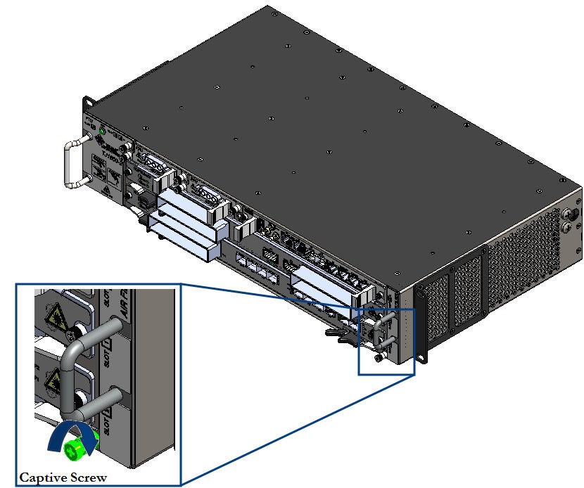 Tightening captive screw on air filter
Eject the air filter
Perform the following steps to eject the air filter from the chassis:
1. Face towards front of the chassis and identify the slot on chassis where the Air Filter is desired to be inserted.
2. Loosen the captive screw that secures the air filter to the chassis using Phillips (PH1) screwdriver. The screw should be loose enough to allow the removal of the card.
Figure 367:  Loosening captive screw on air filter
3. Hold the handle on front panel of the air filter and slide out the unit completely from the chassis while supporting it with your other hand.
Figure 368: 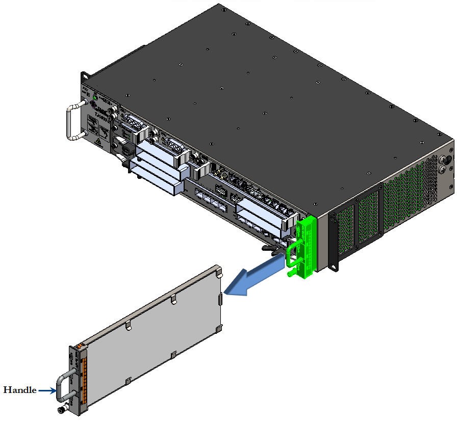 Sliding air filter from the chassis
This section details the procedure for insertion and ejection of cards on a chassis. The cards are provided with ejectors or latch handles that aid in their insertion and ejection from the chassis.
STATIC DISCHARGE DAMAGE: Static charge can damage the equipment. While unpacking and handling cards, or making node interconnections, wear a grounding wrist strap to discharge the static buildup.
CAUTION: If any of the plug-in units or interface modules need to be inserted or ejected, it is imperative that the following procedures are adopted to avoid possible damages to the connectors or spring fingers.
The list of cards having 'ejectors' are given in the following:
• Controller card: OSMC01 card
• Line cards: HCPULine01, HCPSLine01, HCPSLine03, HCPSLine08, HCPSLine12, HCPSLine22, HCPSLine24, HCPSLine25, HCPSLine26, HCPSLine27, HCPSLine28, HCPSLine31, and HCPSLine32
• Ethernet card: CEF-5
• Optical fiber amplifier cards (OFA)
• ROADM
• MDU-16-CL-50G
• MDU-16-D
• OADM4 and OADM1
Prerequisites
Before inserting or ejecting a card, ensure that:
• You have a Phillips (PH1) screwdriver.
• The cables routed from left or right have sufficient slack to remove the card.
• You are properly grounded to the node by an ESD protective wrist strap.
• If the chassis installed on a rack is at a height more that the eye level of the person, use a platform of the required height for easy access and line of sight.
Insert the card
Perform the following steps to insert a card with ejectors into the chassis:
1. Face the front of the chassis and identify the slot where the card has to be inserted.
2. Slide in the card along the guide ways provided on the chassis with ejectors in horizontal open position to engage them to the chassis groove.
Figure 369: 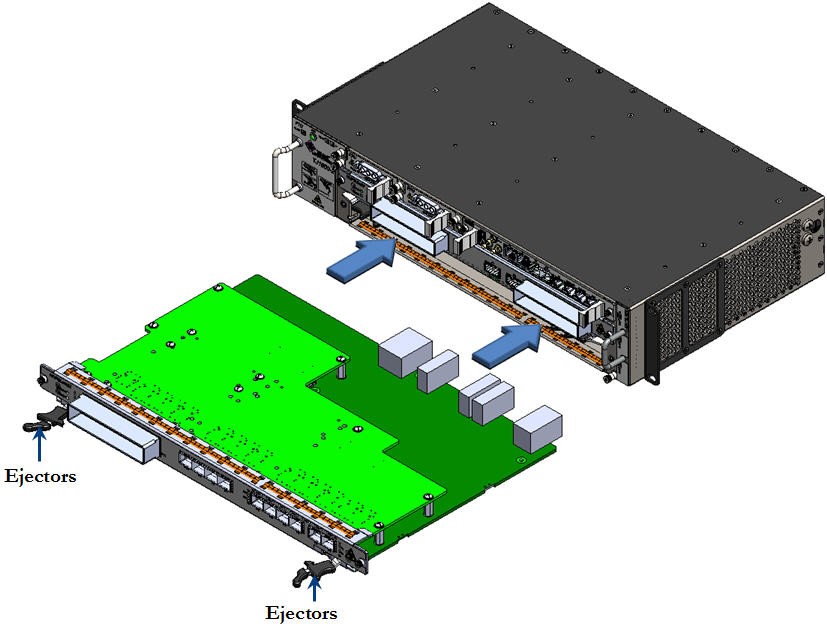 Sliding the card into chassis
3. Operate both the ejectors inwards simultaneously to engage the card to the backplane.
Figure 370: 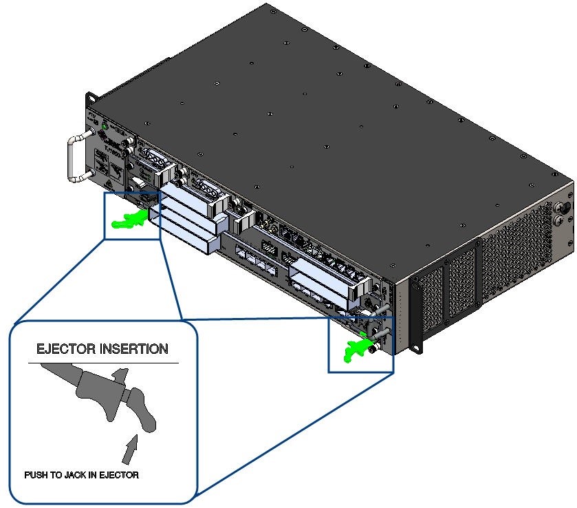 Operating ejectors inwards while inserting
4. Secure the card to the chassis by tightening the captive screws located on both sides of the face plate of the card using Phillips (PH1) screwdriver.
Figure 371:  Tightening captive screws on card
5. Verify that the status LED on the card is green in color which indicates a proper jack in.
RISK OF PERFORMANCE DEGRADATION: If a card is not locked properly to the chassis, it may result in intermittent failures because of poor connectivity. Ensure that the pair of ejectors on the card are properly latched/locked to the faceplate and the captive screws are tightened enough to secure the card on the chassis.
Eject the card
Perform the following steps to eject a card with ejectors from the chassis:
1. Face the front of the chassis and identify the slot from where the card has to be ejected.
NOTE: In case of ejecting cross connect card, press the RST (Reset) switch till LED status displays 'RED' color. Release the switch immediately. Sts (Status) LED displays 'RED' color. During this card goes for booting process. Once the process is complete, Sts (Status) LED displays 'RED BLINKING' color. This indicates that card is ready for removal. Now subtended cross connect card will become main cross connect card.
2. Disconnect all fibers/cables connected to ports on the card.
3. Loosen the captive screws located on both end of the face plate of the card using Phillips (PH1) screwdriver. The screws should be loose enough to allow the removal of card.
Figure 372: 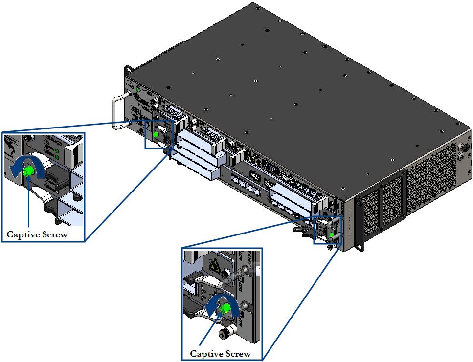 Loosening captive screws on card
4. Hold the two ejectors on the face plate of the card and operate them outwards simultaneously (as shown in the following figure) to disengage the card from the backplane. Wait till the status LED blinks in "Amber" color before pulling out the card from chassis.
Figure 373: 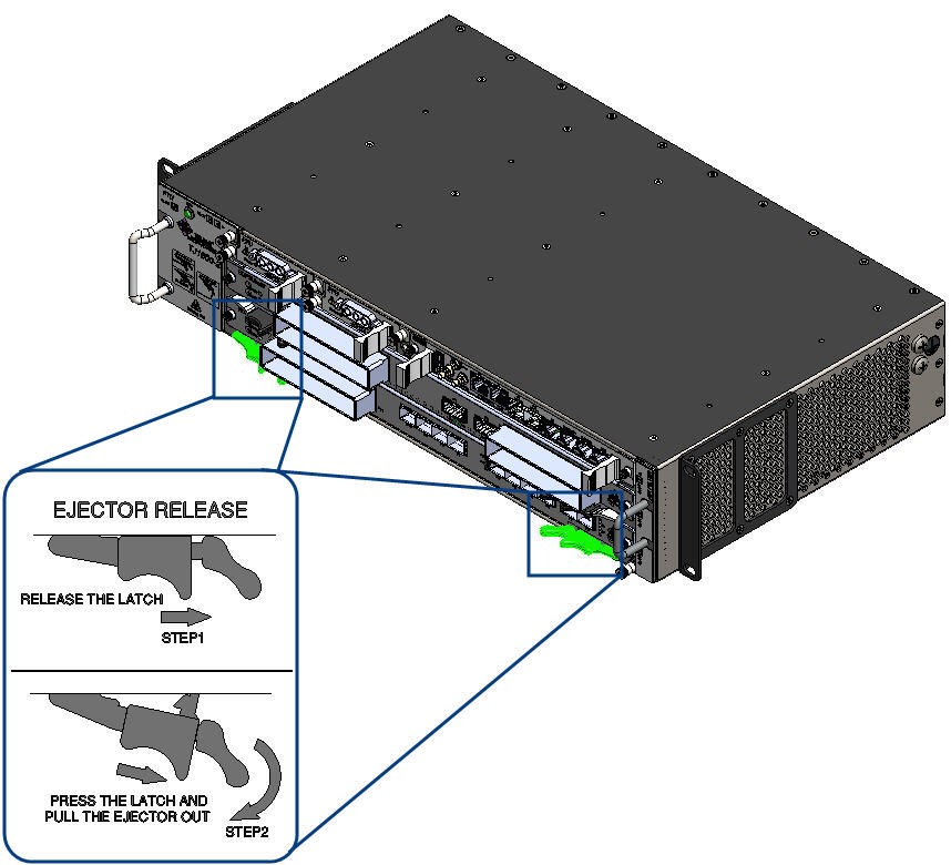 Operating ejectors inwards
5. Slide out the card along the guided ways till it comes out of the slot, while supporting it with your other hand.
Figure 374: 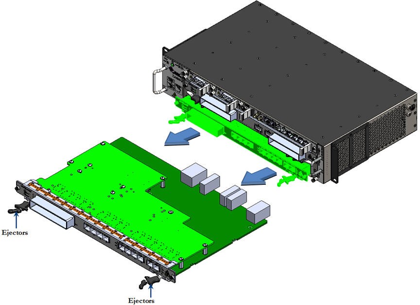 Sliding out the card
NOTE: For HCPSLine08 card, 'Use Early Ejector' option can be enabled or disabled on the node UI. If it is enabled, releasing the latch on ejector triggers the traffic flow on the card to stop before the ejector is pulled out and the card is removed from the backplane. For more details, refer to TJ1600 Product Family User Interface Guide.
20.6.2 Cards with latch handles
The list of cards having 'latch handles' are given in the following:
• OAM and Controller card: OAMC
• MDU-6-D
• MDU-8-D
• VOA
• FPU01
• HCPADP01 and HCPADP02
• HCPADP03 and HCPADP04
• Optical Power Monitoring- OPM-2-C and OPM-4-C
Prerequisites
Before inserting or ejecting a card, ensure that:
• You have a Phillips screwdriver.
• You are properly grounded to the node by an ESD protective wrist strap.
• If the chassis installed on a rack is at a height more than the eye level of the person, use a platform of the required height for easy access and line of sight.
Insert the card
Perform the following steps to insert a card with latch handles in the chassis:
1. Face the front of the chassis and identify the slot where the card has to be inserted.
2. Install the required Adapter card in the slot.
3. Now hold the card to be installed into the adapter card with proper support and slide in along the guide ways. Ensure that the card is inserted in proper slot width.
Figure 375: 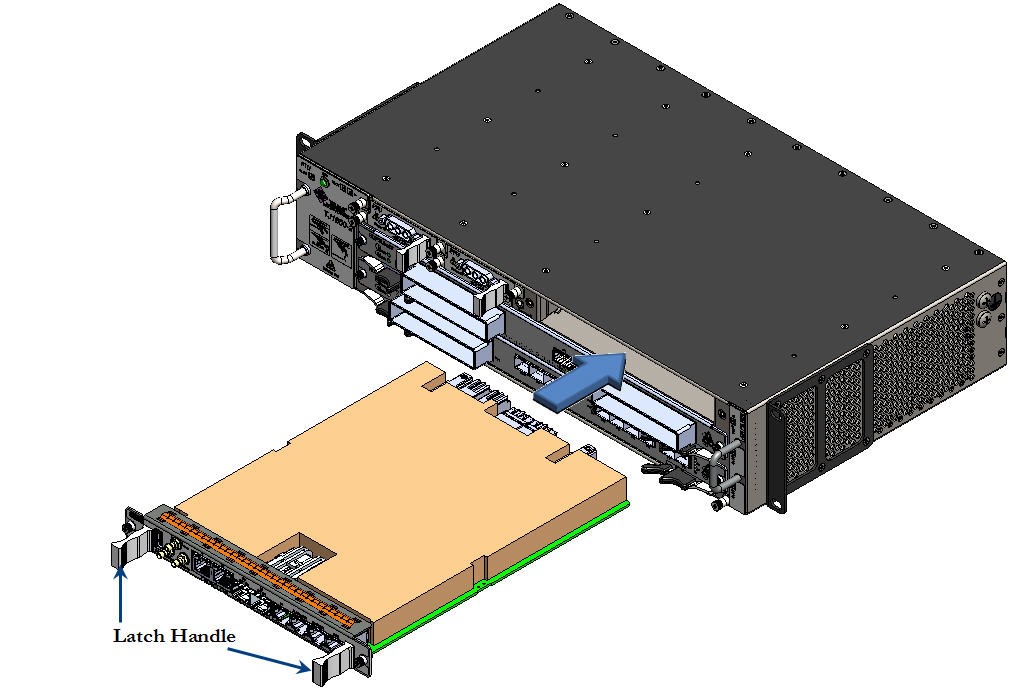 Inserting the card
4. Hold the latch handles provided on the front panel of the card and gently push the card into the chassis to engage it to the backplane connector.
5. Secure the card to the chassis by tightening the captive screws located on both sides of the front panel of the card using Phillips screwdriver.
Figure 376:  Tightening captive screws on the card
6. Verify that the status LED on the card is green in color which indicates a proper insertion.
RISK OF PERFORMANCE DEGRADATION: If a card is not locked properly to the chassis, it may result in intermittent failures because of poor connectivity. Ensure that the pair of ejectors on the card are properly latched/locked to the faceplate and the captive screws are tightened enough to secure the card on the chassis.
Eject the card
Perform the following steps to eject a card with ejectors from the chassis:
1. Face the front of the chassis and identify the slot from where the card has to be ejected.
2. Disconnect all fibers/cables connected to ports on the card.
3. Loosen the captive screws located on both ends of the face plate of the card using Phillips (PH1) screwdriver. The screws should be loose enough to allow the removal of card.
Figure 377: 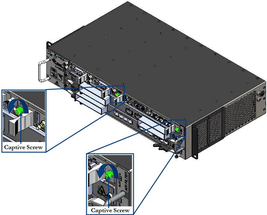 Loosening captive screws on the card
4. Hold the latch handles provided at both ends on the front panel of the card and pull the card gently to disengage it from the backplane. Wait till the status LED blinks in "Amber" color before pulling out the card from chassis.
5. Slide out the card along the guided ways till it comes out of the slot, while supporting it with your other hand.
Figure 378: 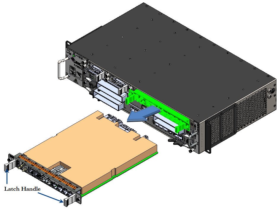 Sliding the card out of the chassis
20.7 Insert and eject the adapter card
This section details the insertion and ejection procedures for the adapter card on a TJ1600 node.
• Optical adapter card HCPADP01 is used to split a slot in TJ1600 chassis to 2/3rd + 1/3rd slots.
• Optical adapter card HCPADP02 is used to split a slot in TJ1600 chassis to 1/2 + 1/2 slots.
The divided slots have backplane support to install the following cards:
2/3rd Slot
• FPU01 with FPUADP01 adapter card
• MDU-8-D
1/3rd Slot
• FPU01
1/2 Slot
• OADM1
• OADM4
• ILU
• OPM4
• VOA
• FPU02
 RISK OF EYE INJURY: Avoid direct exposure to laser beam or fiber as the invisible light can blind the person. Keep all unused optical connectors capped.
Prerequisites
Before inserting or ejecting the adapter card, ensure that:
• You have a Phillips screwdriver.
• You are properly grounded to the node by an ESD protective wrist strap.
• The adapter card is installed first, followed by the active or passive card which are to be inserted in adapter card.
• The active or passive card which are inserted in adapter card is removed first, followed by the adapter card (if required).
• If the chassis installed on a rack is at a height more than the eye level of the person, use a platform of the required height for easy access and line of sight.
NOTE: The procedure is explained for inserting and ejecting HCPADP01 adapter card. Follow the same procedure for inserting and ejecting HCPADP02 adapter card.
Perform the following steps to insert the adapter card into the chassis:
1. Face the front of the chassis and identify the slot where the card has to be inserted.
2. Hold the adapter card (HCPADP01) to be installed with proper support and slide in the card along the guide ways provided on the chassis to the point it easily goes into the chassis. While sliding, position of the card should be horizontal as shown in the following figure:
Figure 379: 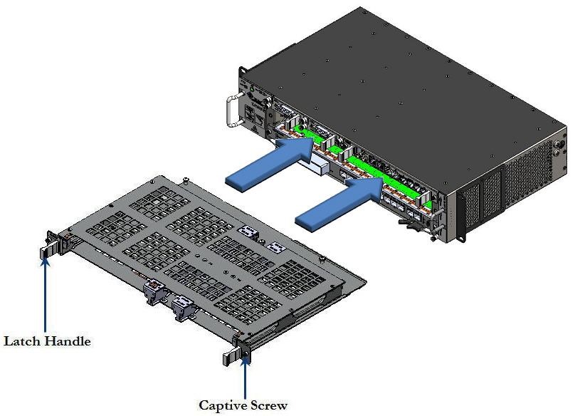 Installing adapter card into the chassis
3. Hold the latch handles provided on the front panel of the card and gently push the card into the chassis to engage it to the backplane connector.
4. Secure the card to the chassis by tightening the captive screws located on both sides of the front panel of the card using Phillips screwdriver.
Insert FPUADP01 into HCPADP01 adapter card
FPUADP01 adapter card is used to house a FPU01 card into 2/3rd slot of HCPADP01 adapter card.
Perform the following steps to insert FPUADP01 adapter card into HCPADP01 card:
1. Face the front of the chassis and identify the slot where the card has to be inserted.
3. Hold the FPUADP01 adapter card to be installed with proper support and slide in the card along the guide ways provided on 2/3rd slot of HCPADP01 card to the point it easily goes into the chassis. While sliding, position of the card should be horizontal, as shown in the following figure:
Figure 380: 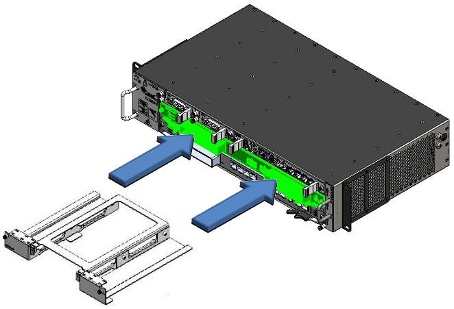 Sliding FPUADP01 adapter card into HCPADP01
4. Secure the adapter card to the chassis by tightening the captive screws located on both sides of the face plate of the card using Phillips (PH1) screwdriver.
5. Now insert the FPU01 card into the slots of FPUADP01 adapter card. Follow the procedure for inserting a card as explained in the topic Cards with latch handles.
Eject the adapter card
Perform the following steps to eject the adapter card from the chassis:
1. Face the front of the chassis and identify the slot from where the card has to be removed.
2. Disconnect the cable connectors from the interfaces (if present) on the desired cards present in adapter card.
4. To remove HCPADP01 adapter card from the chassis, loosen the two captive screws located on both sides of the card. The screws should be loose enough to allow the removal of card.
5. Hold the latch handles on front panel of HCPADP01 adapter card and gently pull out the card to disengage it from the backplane connector.
6. Slide out the adapter card along the guide ways till it comes out of the slot, while supporting it with your other hand.
Figure 381: 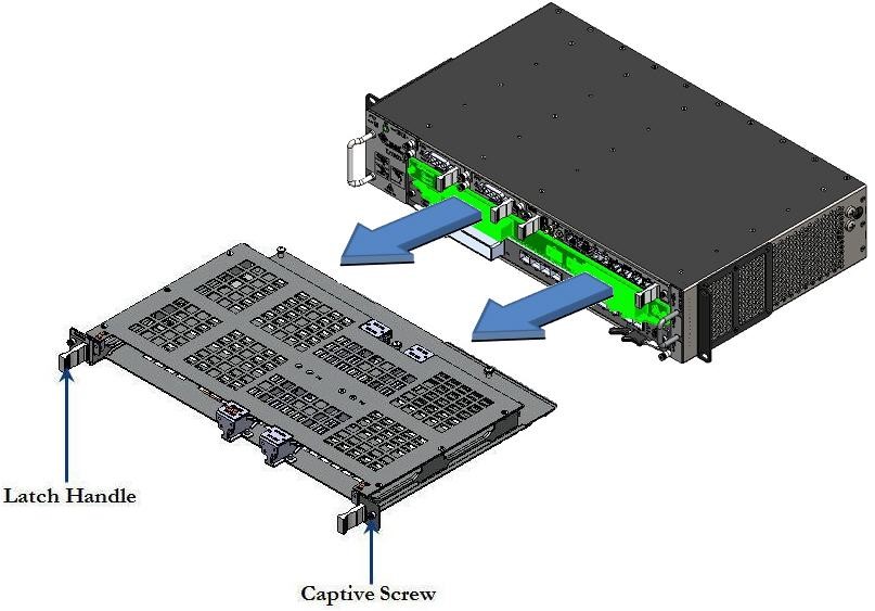 Sliding Out the adapter card from the chassis
20.8 Insert and eject pluggable modules
Before replacing SFP/SFP+/XFP, make sure that the following:
• Replacement transceiver, or a transceiver slot plug
• Antistatic mat
• Rubber safety cap for the transceiver
LASER RADIATION EXPOSURE RISK: Do not look directly into a fiber-optic transceiver or into the end of a fiber-optic cable. Fiber-optic transceivers contain laser light sources that can damage your eyes.
CAUTION: Avoid bending fiber-optic cable beyond its minimum bend radius. An arc smaller than a few inches in diameter can damage the cable and cause problems that are difficult to diagnose.
CAUTION: Make sure that you open the ejector handle completely (you will hear click sound) to prevent transceiver damage.
20.8.1 Insert and eject SFP/SFP+/XFP modules
Follow the procedure for inserting and ejecting SFP/SFP+/XFP modules.
Insert SFP/SFP+/XFP modules
Determine the type of latch SFP transceiver module consists before following the insertion and removal procedures. SFP transceiver modules can have three types of latching devices to secure an SFP transceiver module in a port socket.
SFP transceiver module with a Mylar tab latch.
Figure 382: 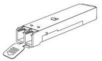 SFP transceiver module with a Mylar tab latch
SFP transceiver module with an actuator button latch.
Figure 383: 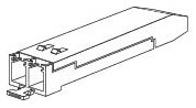 SFP transceiver module with an actuator button latch
SFP/SFP+/XFP transceiver module that has a bail clasp latch.
Figure 384: 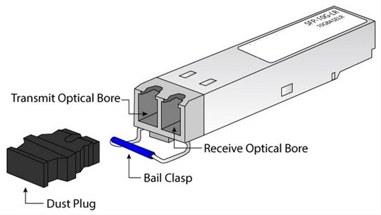 SFP/SFP+/XFP transceiver module having a bail clasp latch
Perform the following steps when inserting transceiver module:
1. Attach an ESD wrist strap to your bare wrist and connect the wrist strap to one of the ESD points on the chassis.
2. Remove the transceiver module from its protective packaging.
3. Verify the label on the module to make sure that the appropriate module to be used in the network port.
4. Place the transceiver module in front of the network port opening.
5. Insert the transceiver in to the port and push gently inwards. For a bail clasp SFP, SFP+, or XFP-Latch (flip upwards) the bail clasp before inserting the SFP, SFP+, or XFP into the slot and then slide it into the slot.
Figure 385: 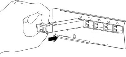 Inserting the transceiver in to the port
NOTE: For modules with an actuator latch, press firmly on both the transceiver faceplate and the actuator button to ensure that the module is properly latched in the socket.
6. A click sound indicates that the module is locked into the port.
7. Verify that the module is latched properly in the socket. Try to remove it without releasing the latch. If the module cannot be removed, it is inserted and positioned properly. If the module can be removed, reinsert it and press harder with your thumb.
8. Remove the dust plugs from the module optical bores.
9. Immediately attach the network interface cable LC connectors to the transceiver module.
Figure 386: 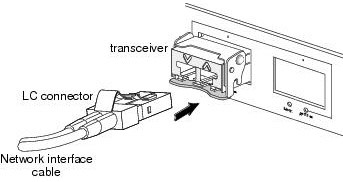 Inserting LC connector cable into the transceiver module
Eject SFP/SFP+/XFP modules
1. Label the cables connected to the transceiver module so that you can reconnect them correctly later.
2. Remove the cable connector plugged into the transceiver module.
3. Place a rubber safety cap over the transceiver.
4. Carefully drape the disconnected cable over the bobbins in the cable management system below the FPC card cage to prevent the cable from developing stress points.
5. Remove the transceiver module from the socket.
— If the transceiver module has a Mylar tab latch, pull the tab gently in a slightly downward direction until the transceiver disengages from the socket connector, and then pull the transceiver module straight out. Do not twist or pull the Mylar tab because you could detach it from the transceiver module.
Figure 387: 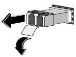 Ejecting pluggable module with Mylar tab
— If the transceiver module has an actuator button latch, gently press the actuator button on the front of the transceiver module until it clicks and the latch mechanism releases the transceiver module from the socket connector. Grasp the actuator button between your thumb and index finger, and carefully pull the transceiver approximately 0.5 inch (1.3 cm) out of the PIC or cFPC straight from the module slot.
» For the 10-port Gigabit Ethernet PIC, use needle-nose pliers or flat-blade screwdriver or other long narrow instrument to pull the ejector handle out from the SFP.
Figure 388: 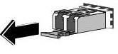 Ejecting pluggable module with actuator button
— If the SFP transceiver module has a bail clasp latch, pull the latch out and down to remove the transceiver module from the socket connector.
NOTE: If the bail clasp latch is obstructed and you cannot use your index finger to open it, use a small flat-blade screwdriver or other long narrow instrument to open the bail clasp latch. Grasp the SFP transceiver module between your thumb and index finger, and carefully remove it from the socket.
Figure 389: 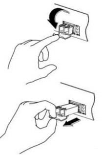 Ejecting SFP/SFP+/XFP transceiver module having a bail clasp latch
6. Place the removed transceiver on an antistatic mat or in an electrostatic bag.
20.8.2 Insert and eject CFP modules
Perform the following procedures for inserting and ejecting CFP modules:
Insert CFP module
1. Attach an ESD wrist strap to your bare wrist and connect the wrist strap to one of the ESD points on the chassis.
2. Remove the transceiver module from its protective packaging.
3. Verify the label on the module to make sure that the appropriate module to be used in the network port.
4. Place the transceiver module in front of the network port opening.
5. Align the CFP device into the transceiver port socket of your networking module, and slide it in until the CFP transceiver EMI gasket flange makes contact with the module faceplate.
6. Press firmly on the front of the CFP transceiver with your thumb to fully seat it in the transceiver socket.
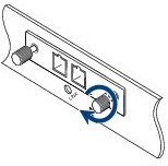
7. Gently tighten the two captive screws on the transceiver to secure the CFP transceiver in the socket.
Figure 390: Tighten the captive screw on CFP
8. Reinsert the dust plug into the CFP transceiver's optical bore until you are ready to attach the network interface cable.
9. When you are ready to attach the network cable interface, remove the dust plugs and inspect and clean fiber connector end faces, and then immediately attach the network interface cable connectors into the CFP transceiver optical bores.
Figure 391: 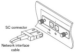 Inserting SC connector cable into the CFP transceiver module
Eject CFP module
1. Label the cables connected to the transceiver module so that you can reconnect them correctly later.
2. Remove the cable connector plugged into the transceiver module. Immediately reinsert the dust plugs in the CFP transceiver optical bores.
3. Loosen the two captive screws that secure the CFP to the networking module.
Figure 392: 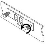 Loosening the captive screws on CFP
4. Slide the CFP transceiver out of the module socket. Immediately place the CFP transceiver in antistatic protective packaging.
Figure 393: 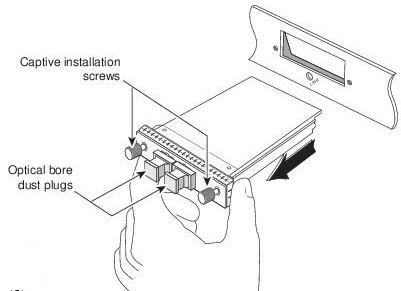 Ejecting CFP module
20.9 Extension power cord gauge calculation
This section provides guidelines to size the power cable conductor for extending the cable length beyond the standard 3m cable supplied with nodes.
As a standard installation kit Tejas nodes are supplied with 3m power cord which is sufficient to wire within the 42U rack. In some installation cases, as part of customer requirement, this cable length need to be increased, may be to power multiple NE's and other collocated instruments. Excess cable length causes voltage drop on the cable which may interrupt the systems operation, especially when the source voltage drops below 40V. The online tool explained in the following helps to calculate the voltage drop on the cable and size the cable according to the requirement.
Calculation
To calculate the gauge of power cable, access the following link:
1. http://www.calculator.net/voltage-drop-calculator.html?material=aluminum&wiresize=1.296&voltage=230&phase=ac3&noofconductor=1&distance=200&distanceunit=meters&eres=20&x=64&y=12
2. The following fields are displayed in the link. Enter the desired values by referring to the table Voltage drop calculator parameters.
Figure 394: 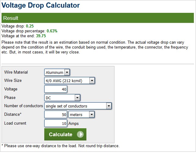 Voltage drop calculator parameters
3. Click Calculate. The result is displayed.
4. The "Voltage drop" shall be less than 0.5V. In case the voltage drop is more than 0.5V, change the attribute Wire size and calculate again until the voltage drop falls below 0.5V. The "Voltage at the end" in the result shall be greater than 39.5V.
5. To convert American Wire Gauge (AWG) to mm2, in the same above mentioned website has Typical AWG wire sizes are given. Use the table to arrive at suitable wire size. Since the table is made for AWG Indian equivalent mm2 wires may not be available off the shelf. In such case choose the next higher wire size available for usage.
Parameters | Description | Action to be taken |
|---|---|---|
Wire material | Select the type of wire material (Aluminum/Copper/Silver/Gold). | Select “Copper” |
Wire size | Choose the wire gauge. | Choose the wire gauge until the Voltage drop result fall below 0.5V. |
Voltage | Enter the supply voltage. | Enter 40V. 40V is the lowest operating voltage supported by nodes. |
Phase | Select the DC, AC single phase, AC 3-phase. | Select DC |
Number of conductors | Select number of parallel conductors. | Select single set of conductors |
Distance | Enter the distance and select the unit. | Select unit as meters and enter the length of the cable from power source to the rack/equipment power inlet. This calculator takes care of round trip wire length (return cable). Enter only one way distance. |
Load current | Enter the current requirement in Amps. | It is recommended that the user enters the amperes considering the total number of chassis that can be placed in the rack even though the present requirement does not demand for it. |
AWG | Area (mm2) |
|---|---|
0000 (4/0) | 107 |
000 (3/0) | 85 |
00 (2/0) | 67.4 |
0 (1/0) | 53.5 |
1 | 42.4 |
2 | 33.6 |
3 | 26.7 |
4 | 21.2 |
5 | 16.8 |
6 | 13.3 |
7 | 10.5 |
8 | 8.37 |
9 | 6.63 |
10 | 5.26 |
11 | 4.17 |
12 | 3.31 |
13 | 2.62 |
14 | 2.08 |
15 | 1.65 |
16 | 1.31 |
While handling a microSD disk, sweat and skin oils may form a film on the contact terminals of the microSD disk. This may lead to poor connection when installed in socket which can result in corruption of microSD disk. To avoid such contamination, take the following precautionary measures for the instances given in the following:
• In-production
— Use clean hand gloves when handling microSD disk.
— Do not touch the gold plated terminal with bare hands.
Figure 395: 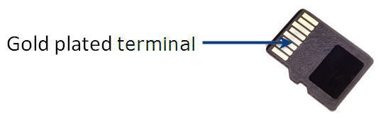 Gold plated terminal of microSD disk
— Clean disk contacts with isopropyl alcohol before final installation into the system.
• In-field
— Before switching ON the power of the system, take out the microSD disk from socket (connector used is push-push type) by holding edges of microSD disk.
Figure 396:  Technique for proper holding of disk
— Wipe the gold plated terminal with a lint-free, clean cloth soaked in isopropyl alcohol. Ensure not to touch the gold plated terminal with bare hands while cleaning.
— After wiping and drying the microSD disk, place the disk back into the socket and then plug the card into system.
Recommended microSD disk size
Following table lists the recommended microSD disk size to be used in the cards with processor:
Cards | Size |
|---|---|
HCPSLine12 | 2GB |
OSMC01 | 4GB |
OAMC | 4GB |
CEF-5 | 2GB |
HCPSLine24 | 2GB |
HCPSLine25 | 2GB |
HCPSLine26 | 2GB |
HCPSLine27 | 2GB |
XCC03 | 4GB |
XCC04 | 4GB |
NOTE: The disk partition will vary for different RHEL versions; hence it is recommended that the disk programming operation is performed by field personnel only.