5 OTN
This chapter covers prominent OTN features supported on TJ1600 product family.
The OTN provides transmission, multiplexing, routing, management, supervision, and protection of client services based on the optical channels. The main feature of the OTN is the transmission and configuration of any digital signals which are irrelevant to client's customized features.
5.1 OTN Protections
• Inherent protection: This protection uses the dual fed and selective receiving function of the electrical layer ODU cross-connections. The protection switching is triggered by defects detected at the ODUk layer (for example, server layer trail and server/ODUk adaptation function).
• Non-intrusive protection: This protection use the dual fed and selective receiving function of the electrical layer ODU cross-connections. The protection switching is triggered by a non-intrusive monitor of the ODUk/ODUj trail.
• Client non-intrusive: This protection uses the dual fed and selective receiving function of the electrical layer ODU cross-connections to protect SDH/ETH/FC services at the client side within or across line cards. For faults on client side, uni-directional protection switching occurs.
• Y-cable protection: The Y-cable splits the client optical signal (from router or other device) and feeds it to two different clients on transponder or muxponder cards. In other directions, it combines the signal received from work and protect client ports. Here, the node takes decision of which client to send the signal towards client interface that is at a time one of the client laser will be ON and other client laser will be in OFF state. The work and protect client laser is controlled for protection switching based on network side faults. The following figure shows how the near-end and the far-end jointly protect against defects when configured from west to east.
Figure 1: Y-cable protection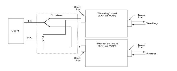
• Compound link SNC group inherent: Protect ODU is non-channelized at the time of provisioning and the work ODU is channelized. On protection creation, the protect ODU will automatically get channelized. This monitoring type is allowed at ODUk level only and not at ODUj level. Supported only on 1+1 without APS bytes architecture with unidirectional switching mode.
5.2 Link integrity
Allows to detect faults along the end-to-end Ethernet transport connection. When Link integrity is enabled, the following faults forces the Ethernet port laser to go down.
• Near-end Ethernet link failure
• SDH/OTN link failures
• CSF/Far-end Ethernet link failure
5.3 Idle frame
This frame is also known as control frame and consists of only a core header field with no payload area. When idle frame is enabled, the Ethernet ports emit idle frames for a predetermined amount of time in response to OTN network problems.
Idle frames are dummy frames added to the transmission link to prevent flapping of client devices due to network faults. This is a useful feature to enable and configure when the network is designed with protection in lower layers such as OTN, DWDM. One may like to prevent the flapping of end client device during the momentary link down happening during the switching event between active to stand-by path in the network. The Idle frame insertion helps in pumping in dummy frames during this momentary glitch which in turn results in end device not seeing the faults and thus remaining active and not triggering a switching or flapping.
Enabling/disabling idle frames is a user defined parameter. It is set at each client interface/port on the selected hardware/ports where the feature is supported. You have flexibility to define the idle frame timer which acts as a watch-dog to insert the idle frames from the trigger till the timer runs out. The post timer expiry, the idle frames are stopped from being injected into the transmission link. Any fault that continues past the idle frame timer value will therefore be reported to end devices, indicating a transmission link error.
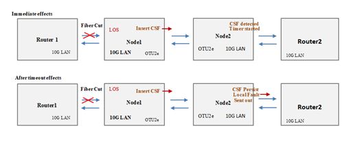
Figure 2: Timed link fault action
NOTE: Idle frame is supported only for 10GE (only BMP mapping) clients with Timing transparent mapped (TTM).
In OTN network, for client/line side faults, after receiving alarm on client ODUk, the corresponding Ethernet client sends Local Fault signal to the near end connected router port and far end router receives Remote Fault. After fault restores, client stops sending Local Fault signal.
Scenario 1:
Figure 3: Link fault action along with the timer-1
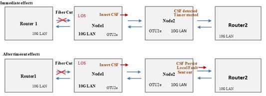
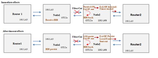
Scenario 2:
Figure 4: Link fault action along with timer-2
NOTE: Local fault or remote fault is supported only for 10GE clients with Timing Transparent mapped (TTM).
5.5 RPP
The Regenerators Port Pairing (RPP) in the link, if fault occurs on one side other side line port still transmits power. The far end node if any optical line protections (OLP/FPU) configured that will not get loss of signal (LOS) and switching will not happen and traffic goes down. With this feature, if any fault received in regenerators one port, other port turns off the laser. Now, far end node receive LOS and protection switches to other path.
NOTE: RPP is supported only on transponder mode.
5.6 NPP
The Network Port Protection (NPP) uses the dual feed and selective receiving function of the electrical layer. The ODU cross-connections to protect OTN line side within same line card. For faults on line side, uni-directional protection switching occurs.
NOTE 1: NPP is supported only in transponder mode.
NOTE 2: Inherent protection, non-intrusive protection, and NPP are supported only for OTN ports.
5.7 FEC
The Forward Error Correction (FEC) enables the detection and correction of errors in an optical link. FEC has proved to be efficient in correcting a very high number of errors in transmission due to noise or other impairments present in high-capacity transmissions thus improving the signal to noise ratio of the signal.
For ITU G.709 the FEC code used is a Reed-Solomon RS (255,239)
For OTU2/OTU2e, GFEC (RS) and EFEC types are supported.
For OTU4 (non-coherent CFP), only GFEC (RS) is supported.
For OTU4/OTUCk (coherent CFP/CFP2), HDFEC, SDFEC, SDFEC-ND, SCFEC and Transparent are supported.
NOTE: Pre FEC SD alarm supported on OTU4/OTUC1/OTUC2 port.
5.8 HCPSLine22 - OTN FEC summary
The HCPSLine22 OTN FEC summary is as follows:
Figure 5: HCPSLine22 OTN FEC summary 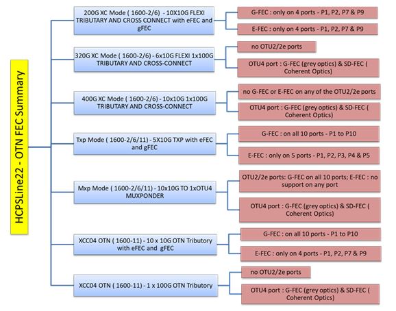
5.8.1 AGG200:HCPSLine22 - feature table
The HCPSLine22 feature table provides port details for supported features.
Figure 6: AGG200: HCPSLine22- Feature Table
5.8.2 AGG200G - HCPSLine12/24/25/26/27/28 feature table
Figure 7:  AGG200G- HCPSLine12/24/25/26/27/28 Feature Table
5.9 Single Fiber/Uni-directional Crossconnects (100G Network)
Single fiber solution is a special case of optical communication transmission which uses single fiber strand for bidirectional traffic transmission as against the traditional approach of fiber strand pair.
It has functional edge in networks or topologies where fiber core availability is scarce.
This has a large economic impact on carriers, dark fiber providers and enterprises where the cost of ownership or leasing out costs are enormous.
Using an uni-directional cross-connection feature of OTN DXC in TJ1600-2/TJ1600-6/TJ1600-11, we achieve the single fiber solution.
The solution is transparent to the client interface type and support SDH, SONET, SAN, Ethernet, OTN clients in the single fiber solution.
Figure 8: Single Fiber solution overview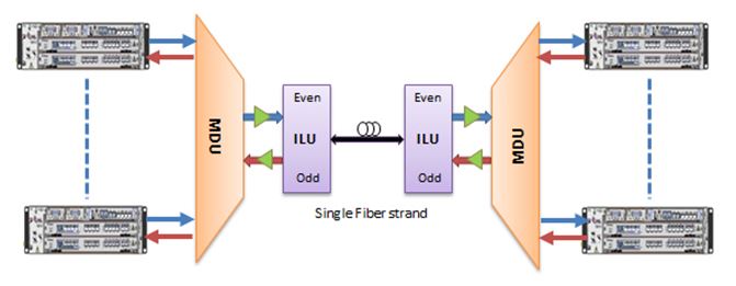
NOTE 1: On the TJ1600-2/6 400GXC node, unidirectional cross connect is supported.
NOTE 2: Uni-directional cross connect with ODU-SNCP protection is supported.
NOTE 3: Uni-directional cross connect with Y-cable protection is supported.