This chapter describes the node commissioning procedures you must perform on a newly installed node. The node commissioning is performed using the web user interface by providing the commissioning data of the node. The commission and test report is used to record the commissioning data of a node.
15.1 Configure parameters in SLAT page
Ethernet IP
Each node has a network management system (LAN/NMS) port which is a 10/100 Mbps network interface controller (NIC) port. Ethernet IP is the IP address with which the node communicates with the external world.
Subnet mask length
The subnet mask length is an optional parameter that corresponds to the Ethernet IP address. Subnetting is used to set the subnet mask parameters.
NOTE 1: The subnet mask for a point-to-point connection (that is, a direct Ethernet connection between the WUI host and the node) should be set to 32.
NOTE 2: If there are any failures after the node is up and configured, the you will still be able to reach the node if it goes to the SLAT page.
Router ID
Node communicates in the network over the Embedded Communication Channel (ECC), using the router ID. A node can be configured either as a gateway element (interconnecting two networks) or just a pass-through node.
Follow the steps before configuring the Ethernet IP, subnet mask, router ID, and rate on the node:
1. Log into node WUI using the LAN/NMS port.
2. Ensure your PC is correctly connected to the node through the LAN/NMS port.
3. Ensure that you have the Ethernet IP address, router ID, sub net mask, and static route IP of the node to be configured.
4. Ensure the PC is configured in the same LAN as the node.
Follow these steps to configure the node's Ethernet IP, subnet mask, router ID, and rate:
1. Click Initialize Node Parameters. The Configure Slat Node page appears.
Figure 298: 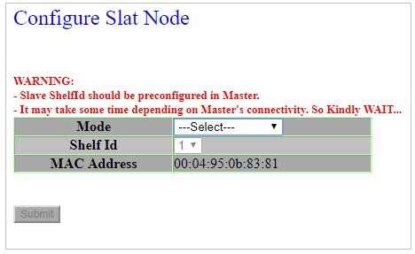 Configure slat node
2. Select the Mode as Main from the drop down.
3. Select the Shelf Id as 1 (Selected by default). The MAC address field displays the MAC address of the chassis.
4. Click Submit. The Initialize Node Parameters page of TJ1600-2 appears as shown in the following:
Figure 299: 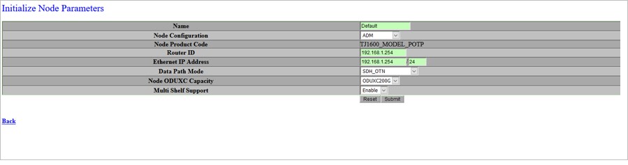 Initialize node parameters- TJ1600 Type-2SR
Following figure shows the Initialize Node Parameters page of TJ1600-6:
Figure 300: 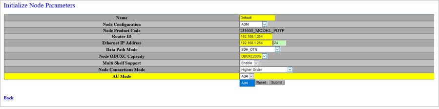 Initialize node parameters - TJ1600-6
Following figure shows the Initialize Node Parameters page of TJ1600-11 with HCPXCC03:
Figure 301:  Initialize node parameters- TJ1600 Type-11SR with HCPXCC03
Following figure shows the Initialize Node Parameters page of TJ1600-11 with HCPXCC04 (640G):
Figure 302: .jpg) Initialize node parameters- TJ1600 Type-11SR with HCPXCC04 (640G)
Initialize node parameters- TJ1600 Type-11SR with HCPXCC04 (640G)
Following figure shows the Initialize Node Parameters page of TJ1600-11 with HCPXCC04 (900G):
Figure 303: .jpg) Initialize node parameters- TJ1600 Type-11SR with HCPXCC04 (900G)
Initialize node parameters- TJ1600 Type-11SR with HCPXCC04 (900G)
Following figure shows the Initialize Node Parameters page of TJ1600-11 with OSMC card:
Figure 304: 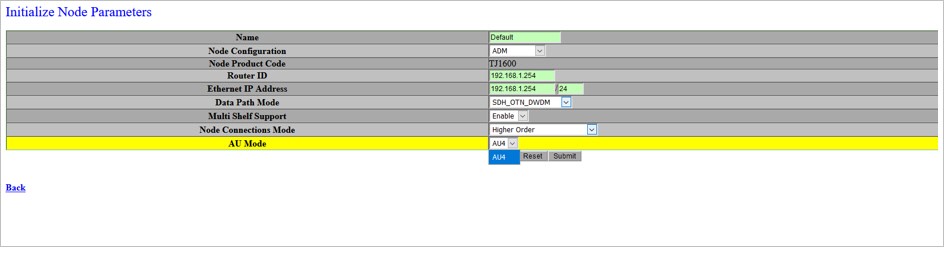 Initialize node parameters page of TJ1600-11 with OSMC card
5. Enter the node name in the Name field.
6. Enter the functional router ID of he network in the Router ID field.
7. In the Ethernet IP field, the IP address must be entered. The Ethernet IP of each node in the network must be unique.
8. Do one of the following:
— For TJ1600-2: Select Data Path Mode as SDH_OTN/SONET_OTN, Node ODUXC Capacity as ODUXC200G/ODUXC400G from the drop down menu.
— For TJ1600-6: Select Data Path Mode as SDH_OTN/SONET_OTN, Node ODUXC Capacity as ODUXC200G/ODUXC400G, Node Connections Mode as Higher Order and AU Mode as AU4.
— For TJ1600-11 with HCPXCC03: Select Data Path Mode as SDH, Node Connections Mode as Higher Order and AU Mode as AU4.
— For TJ1600-11 with HCPXCC04 (640G): Select Data Path Mode as SDH, Node Connections Mode as Higher Order and AU Mode as AU4.
— For TJ1600-11 with HCPXCC04 (900G): Select Data Path Mode as OTN, Node Connections Mode as Higher Order and AU Mode as AU4.
— For TJ1600-11 chassis, to configure SONET mode with HCPXCC04, from the SLAT page select Data Path Mode as SONET_OTN_DWDM, Node Connection Mode as Higher Order and AU Mode as STS1.
— For TJ1600-11 with OSMC card: Select Data Path Mode as SDH_OTN_DWDM/SONET_OTN_DWDM, Node Connections Mode as Higher Order and AU Mode as AU4.
9. Select Multi Shelf Support as Enable from the drop down menu.
10. Click Submit. A confirmation page appears.
11. Click Accept Valid Modifications. A node reboot warning appears.
NOTE 1: The node name can be alphabetic/numeric/alphanumeric consisting of 1-20 characters. Special characters can also be used, except space.
NOTE 2: The default router ID displayed is 192.168.1.254. The node IP is to be set as 192.168.1.xxx, where xxx must be between 1 to 253. The last octet of the router ID and Ethernet IP must not be provisioned as 0 and 255 as they are reserved addresses and therefore should not be provisioned.
NOTE 3: The default Ethernet IP displayed is 192.168.1.254.
NOTE 4: The node reboots after the Ethernet IP, subnet mask, and the router ID are entered. After the node is up, verify whether all the changes are reflected. If the changes are not reflected correctly, contact your next level of support. The PC IP configuration must be updated to ensure connectivity to the newly provisioned IP address for the node. Software version appears in the description field of the default WUI page. The software version is in the format x.y, where x is the major release and y is the minor release.
15.2 Connect PC to LAN/NMS port of the node
Before connecting the PC to the LAN/NMS interface of the TJ1600-2 node, follow the steps:
• Ensure that you have a PC and an Ethernet cable with an RJ-45 connector.
• Ensure that you have the node IP address information, if the node has already been commissioned.
NOTE: After powering up the node you have to wait for few minutes for the node software to be up. This time depends on the cross connect card being used. The Status/Active LED indicates the up status of the node. The IP address of the PC should be in the same IP subnet as that configured on the node. If the node is getting commissioned for the 1st time then use any address of PC other than 192.168.1.254 in 192.168.1.0 subnetwork.
To connect the PC to the LAN/NMS interface of the node, follow the steps:
1. Connect the LAN/NMS port of the node and the PC terminal with an Ethernet cable of RJ-45 connector type.
2. Configure the IP address of the PC to be in the same subnet as the node.
3. If the preceeding steps fail, check whether that you have used correct cables.
NOTE: While connecting to an uncommissioned node, your PC IP address must be 192.168.1.xxx where xxx is between 1 and 253. While connecting to commissioned node, your PC IP address must reside in the same subnet as the node. Also, configure the PC subnet mask to match the node's subnet mask and the PC default gateway must be in the same LAN/NMS gateway.
15.3 Connect PC to LNMS ports of the node
Before connecting the PC to the LNMS interface of the TJ1600-6 node, follow the steps:
• Ensure that you have a PC and an Ethernet cable with an RJ-45 connector.
• Ensure that you have the node IP address information, if the network element has already been commissioned.
NOTE: After powering up the node, wait for few minutes for the node software to be up. This time depends on the cross connect card being used. The Status/Active LED indicates the up status of the node. The IP address of the PC should be in the same IP subnet as that configured on the node. If the node is getting commissioned for the 1st time then use any address of PC other than 192.168.1.XXX in 192.168.1.XXX subnetwork.
To connect the PC to the LNMS interface of the node:
1. Connect the LNMS port of the node and the PC terminal with an Ethernet cable of RJ-45 connector type.
2. Configure the IP address of the PC to be in the same sub net as the node.
3. If the preceeding steps fail, check whether that you have used correct cables.
NOTE: While connecting to an uncommissioned node, your PC IP address must be 192.168.1.XXX where XXX is between 1 and 253. While connecting to commissioned node, your PC IP address must reside in the same subnet as the node. Also, configure the PC subnet mask to match the network element's subnet mask and the PC default gateway must be in the same LNMS gateway.
15.4 Download software from SLAT page
System Line-up and Test (SLAT) is used for new configuration of the node.
Before downloading the software from SLAT page, ensure that you have:
• PC and an Ethernet crossover cable with RJ-45 connector.
• Node IP address information if the node is already been commissioned.
To download software from SLAT page, ensure the following:
1. Connect the laptop with static IP 192.168.1.x to the node so that, it can be accessed.
2. Launch Mozilla 38.0.0/Microsoft Edge 108.0.1462.54/Google Chrome 108.0.5359.125 of the browser and enter the URL https://192.168.1.254 or http://192.168.1.254:20080.
— Restore from a previous back up configuration.
— Initialize node parameters.
— Install the software to proceed.
3. Click Please install the software to proceed.
4. Select the following software download options:
— Deliver release from local machine.
— Deliver release from remote machine.
5. If local machine is selected, provide the path of the file.
6. If a remote machine is selected, provide the following:
— Username
— Password
— IP of remote machine
— FTP (optional)
— Directory
7. Click Submit. The new software is downloaded to the NE. On completing the download, the system prompts you to initialize the node parameters such as Node Name, Ethernet IP address, location, and Router ID.
On initializing the node parameters, node goes for warm reboot while the node is rebooting the software initializes on the NE. Once the node is up, issue a service disruptive reboot for the FPGAs to get programmed on the NE.
NOTE: After restoring the new database, the node requires a hard reboot for the new configuration to take effect. You can verify the software version from the description field of the default WUI page. The software version is in the format x.y, where x and y represents major and minor release respectively.
15.5 Log into an uncommissioned node
Before logging into an uncommissioned node, ensure that the PC is connected to the LAN/NMS port of the node through a crossover cable with RJ-45 connectors.
NOTE: Change the default username for the default user account on the node. The default user account and password are widely known.
Follow the procedure to login to an uncommissioned node:
1. Launch Mozilla 38.0.0/Microsoft Edge 108.0.1462.54/Google Chrome 108.0.5359.125 of the browser and enter the URL https://192.168.1.254 or http://192.168.1.254:20080. The default IP address of the LAN/NMS port is 192.168.1.XXX and can be changed.
NOTE: By default, http is disabled. It can be enabled from node UI under Security menu. For more details, refer to TJ1600 Product Family User Interface Guide.
2. If the node does not respond, check the physical connection. Otherwise, contact your next level of support.
3. If the login screen appears, enter the default user id and password at the login prompt:
— Default Username: tejas
— Default Password: j72e#05t
— Domain: Local
NOTE: Ensure the domain is always Local.
The navigation menu of the node is displayed. The node view is the default page of the WUI. If the default page of the WUI does not appear or login failed, check whether the user id and password entered are correct. The user ID and the password rules are as follows:
15.6
Parameters | Rules |
|---|---|
Username | • is unique. • can be alphabetic/numeric/alphanumeric. • supports special characters except space. • supports up to 32 characters. |
Password | • is unique. • is eight characters long only. • can be alphabetic/numeric/alphanumeric. • supports special characters except space. |
Follow the steps to set the date and time of the node:
Setting date and time for a node
1. Click System Time in the navigation pane.
2. Click Set Time link. Set Node Time page appears.
3. Set date and time by selecting appropriate values from the drop-down menu.
4. Click Submit. The changes are applied and a confirmation message appears.
Setting time zone for a node
1. Click System Time in the navigation pane.
2. Click Set Time Zone link. Set Time Zone page appears.
3. Set the time zone by selecting appropriate value from the drop-down menu.
4. Click Submit.
5. The changes are applied and a confirmation message is displayed. In case the drop down menu does not display the desired time zone, click Other Time Zones. The Other Time Zones page appears.
6. Enter the name of the time zone, the offset value, Enable Day light saving from drop down menu. Set the Day light saving time parameters as:
— Month
— Week
— Day
— Hour
— Minute
7. Click Submit. The changes are applied and a confirmation message is displayed.
Setting time server for a node
1. Click System Time in the navigation pane.
2. Click Set Time Server link. Set Time Server page appears.
3. Enable the field NTP Client Enable.
4. Enter the IP address of the server from which the node is to derive the date and time.
5. Select the Synchronization interval from the drop-down menu.
6. Click Submit. Changes are applied and a confirmation message is displayed.
NOTE: Set the timing server of stratum level to 14 or less than 10. The node does not synchronize to the server if the stratum level is not within the specified range. NTP servers provisioned may take five minutes to update current NTP server parameter.
15.7 Verify the serial numbers of cards and pluggable modules of the node
Follow the steps to verify the serial numbers of the chassis and the cards present in the node:
1. Click Inventory in the navigation menu.
2. Click Node Inventory link. The Node Inventory page appears.
3. View the serial numbers of all the cards in the Node Inventory page.
4. Verify the serial numbers of all the cards with the shipment report.
5. Verify whether all the cards present in the chassis are listed with the correct information in the WUI Inventory application.
6. Verify whether the Power LED is turned on with green color for all the cards.
15.8 Set node date and time
Follow the steps to set the date and time of the node:
Setting date and time for a node
1. Click System Time in the navigation pane.
2. Click Set Time link. Set Node Time page appears.
3. Set date and time by selecting appropriate values from the drop-down menu.
4. Click Submit. The changes are applied and a confirmation message appears.
Setting time zone for a node
1. Click System Time in the navigation pane.
2. Click Set Time Zone link. Set Time Zone page appears.
3. Set the time zone by selecting appropriate value from the drop-down menu.
4. Click Submit.
5. The changes are applied and a confirmation message is displayed. In case the drop down menu does not display the desired time zone, click Other Time Zones. The Other Time Zones page appears.
6. Enter the name of the time zone, the offset value, Enable Day light saving from drop down menu. Set the Day light saving time parameters as:
— Month
— Week
— Day
— Hour
— Minute
7. Click Submit. The changes are applied and a confirmation message appears.
Setting time server for a node
1. Click System Time in the navigation pane.
2. Click Set Time Server link. Set Time Server page appears.
3. Enable the field NTP Client Enable.
4. Enter the IP address of the server from which the node is to derive the date and time.
5. Select the Synchronization interval from the drop-down menu.
6. Click Submit. The changes are applied and a confirmation message appears.
NOTE: Set the timing server of stratum level to 14 or less than 10. The node does not synchronize to the server if the stratum level is not within the specified range. NTP servers provisioned may take five minutes to update current NTP server parameter.
15.9 Synchronization reference clock source for the node
Follow the steps to nominate a synchronization reference clock source for the node:
1. Click Configuration in the navigation pane.
2. Click Synchronization > Nominate Timing Reference. The Nominate timing references page is displayed.
3. Select the Clock Reference type for a node. Set the clock reference port and the priority for the clock reference selected.
4. Click Submit. The changes are applied and a confirmation message appears.
If the clock source is not nominated as expected, contact your next level of support.
15.10 Backup and restore node configuration data
Before backing up or restoring the node configuration data, ensure that:
1. PC/Laptop is connected to the FTP server.
2. IP address of the source/destination for the restore or backup operation is correct.
3. Directory path from where the configuration file is restored from or saved to is correct.
4. Username and password of the FTP account is correct.
NOTE: If you have a Linux or Unix machine, enable the FTP server that comes along with it. If you are using a Windows machine, you must install FTP server such as 3Cdaemon. The FTP server for Windows can be downloaded from the following location: https://3cdaemon.updatestar.com/en for windows 32 bit.htm.
Follow the steps to backup the node configuration data:
1. Click Maintenance > Configuration Management > Backup Configuration in the navigation menu. The Backup configuration page appears.
2. Enter the parameters specified in the Backup Configuration parameters table.
3. Click Submit.
4. Click Accept Valid Modifications. A confirmation page displaying the successful completion of backup operation appears.
The following table describes the backup configuration parameters:
Parameter | Default Value | Description |
|---|---|---|
Configuration Operation | Backup Configuration to Remote Machine | Parameter to select if the configuration is to be backed up to a remote machine or local machine. • Backup configuration to a remote machine: Configuration is backed up to a remote machine. • Backup configuration in the local machine: Configuration is backed up in the local machine. |
User Name | - | The user name of the system where the backup configuration should be saved. |
Password | - | The password of the system on which the backup is to be saved. |
IP Address | - | The IP address of the system where the backup is to be saved. |
FTP Port (optional) | - | The FTP port number for establishing connection to the system where the configuration backup is to be saved. |
Directory | - | The directory in which the configuration backup is to be saved. |
Follow the steps to restore node configuration data:
1. Click Maintenance > Configuration Management > Restore Configuration in the navigation pane. The Restore configuration page appears.
2. Enter the parameters specified in the Restore Configuration parameters table.
3. Click Submit. You are connected to the PC from which you want to restore configuration. Locate the configuration file and click it. The configuration is restored on the node.
4. Click Accept Valid Modifications. A confirmation page displaying the successful completion of restore operation appears.
5. Click Commit for the restored configuration to take effect. The node goes for a cold reboot and the restored configuration takes effect.
NOTE: The remote server must have an FTP server installed on it to carry out the Restore configuration data command. For a Linux system, FTP server is inbuilt. For Windows system, install any third party server such as 3Cdaemon server along with the provided IIS server.
The following table describes the restore configuration parameters:
Table 13: Restore configuration parameters Parameter Default value Description Configuration Operation Restore configuration from remote machine Parameter to select if the backup is available on a remote machine or local machine. • Restore configuration from remote machine: Configuration is restored from remote machine. • Restore configuration from local machine: Configuration is restored from the local machine. User Name - The user name of the system where the backup configuration is present. Password - The password of the system on which the backup is present. IP Address - The IP address of the system where the backup is present. FTP Port (optional) - The FTP port number for establishing connection with system having the configuration backup. Directory - The directory in which backup configuration file is present.
NOTE: After committing the configuration, cold reboot the shelf. The node configuration state is displayed at the bottom of the preview pane.
 CAUTION: The restoration of configuration data of a node is service disruptive. The new configuration data requires backup. Restoration could be done from a system which has an FTP server.