The Power Filter Unit (HCPPFU04) is used in TJ1600 Type-6SR chassis to supply power. The unit provides a filtered input voltage of -40V to -57.6V to the chassis and the cards on the chassis.
There are two HCPPFU04 cards in each system to provide input source redundancy. An EMI filter is used to restrict conducted emissions. The filters have transient voltage suppressors to prevent voltage surges affecting the system.
 STATIC DISCHARGE WARNING: Static charge can damage the equipment. While handling cards for making system interconnections, wear an ESD strap to discharge the static buildup.
 CAUTION: This equipment might have more than one power supply connection. All connection must be removed to de-energize the unit before accessing internal parts for maintenance or service.
 DANGER: Do not jack-in/jack-out PSU/PFU card in the system with Power Cable connected. PSU/PFU has high energy and/or voltage level that can cause serious electrocution or burn.
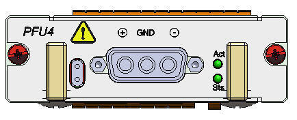
The following figure shows the front panel diagram of the HCPPFU04:

Operational Specifications of Power Filter Unit- HCPPFU04
Specification |
Range |
|---|---|
Input Voltage Range |
-40V to -57.6V DC |
Reverse Polarity Protection |
Continuous |
Input Current |
21A continuous at nominal voltage, 25A maximum at -40V during normal operation. |
Maximum operating Ambient Temperature |
-5°C to 55°C |
Output Voltage |
-40V to -57V DC |
Output Current |
21A |
Efficiency |
>90% Load when input is -48V DC |
Fuse |
40A Telecom fuse |
Under Voltage Protection |
|
Hold-up Time (Interruption) |
1.5ms at -53.2V and above |
Power Interface |
|
Protections |
|
Status Indication |
|
Following are the functional features of the HCPPFU04:
The visual indicators on the HCPPFU04 card include two LEDs namely Act (ACTIVE) and Sts (STATUS), provided to indicate the card status and whether the card has become active.
LED status and their significance- HCPPFU04
Card State |
Sts LED |
Act LED |
|---|---|---|
Card initialization: State before the card initialize is complete on card insertion. |
Amber (Steady) |
Amber (Steady) |
Card in service: Initialization complete and card in service. |
Green (Steady) |
Green (Steady) |
Card mis-match: Node has already configured the slot with some other card. |
Amber |
Amber |
Card failed during boot up. |
Red |
Amber |
Card failed while in-service. |
Red |
Green |