This chapter describes the operations that can be performed under the Tools menu.
Following are the options available under Tools menu:
• BOM to Bayface Tool
• OMS to Path Conversion Tool
Click Tools option menu to view the list of drop-down options and click BoM to Bayface Tool from the options list.
Figure 91:  Page showing list of BOM to Bayface results
This section describes available button in BOM to Bayface Tool page. Following is the button available:
• Add New BOM: Click Add New BoM button which is available at top-right corner to perform BOM to Bayface conversion for a network.
11.2.2 List of active BOM to Bayface results
This section describes table showing list of BOM to Bayface tool results. Following are the columns:
• Sl.No: Serial number is used to enumerate the list of BOM to Bayface results
• Network Name: Displays the name of the network
• Time Stamp: Displays the time stamp of the network
• Bayface Configuration: Displays the name of the configuration
• Actions: This column has maximum two buttons as listed below
— View: Click View button to view the BOM to Bayface result.
— Download: Click Download button to download the BOM to Bayface result in excel format.
11.2.3 BOM to Bayface conversion procedure
This section describes how to perform BOM to Bayface conversion of a network.
Follow the steps to convert BOM to Bayface network:
1. Click Add New BoM button which is at the top-right corner. After clicking on the button a new form as opens up.
2. Following are the form parameters:
— Name of the Network: Provide name for the network
— Brief Description: Provide a small description of the network. This field is optional.
— Unused slots required: This option allows the user to add number of unused slots required on each chassis in the bayface diagram of a network.
— Bayface: In combined optical and electrical cards option, both optical and electrical components will be placed in the same chassis. In separated optical and electrical cards option, optical and electrical components are placed in different chassis.
— BoM data in excel file: Allows the user to import BOM excel sheet. Only excel document with file extension .xlsx is supported. Leftclick on Choose File button and browse into your system, select the input excel sheet to upload the network BOM.
3. Fill the form and click Submit to save data.
4. Each excel file should have one sheet with name Bill of Materials
NOTE: Ensure only one sheet present in the input excel file. User can upload network design output Bill of Materials sheet as input sheet by excluding Node Type and Node Degree rows.
Bill of Materials input sheet lists all the device TPNs of a network and their details. Following are the column of BOM to Bayface input sheet.
— TPN: TPN of the device used in network design
— Name: Name of the device used in network design
— Description: Simple description of the device
— TPN Count: T PN count corresponding to the node used in the network design. The number of nodes depends on the network. There is one column for each node with node name as column heading.
11.2.4 View BoM to Bayface result
Following are the steps to view the BOM to Bayface results:
1. Go to List of Active BOM to Bayface results
2. Click View button, which is present in table showing list of active BOM to Bayface results
3. Following are the tabs within the BOM to Bayface result page:
— BOQ: Based on the cards in the input BoM, the tool populate the chassis and required commons in the BOQ similar to the ones in the output file
— BoM: Based on the cards in the input BoM, the tool populate the chassis and required commons in the BOM similar to the ones in the output file as shown in figure
— Bayface: Based on the cards in the input BoM, the tool populate the chassis in the Bayface diagram.
Figure 92:  Page showing tabs: BoQ/BoM/Bayface
11.2.5 BoM to Bayface result in excel format
This section describes BoM to Bayface tool result in excel format. Following are the excel sheets of BoM to Bayface tool results:
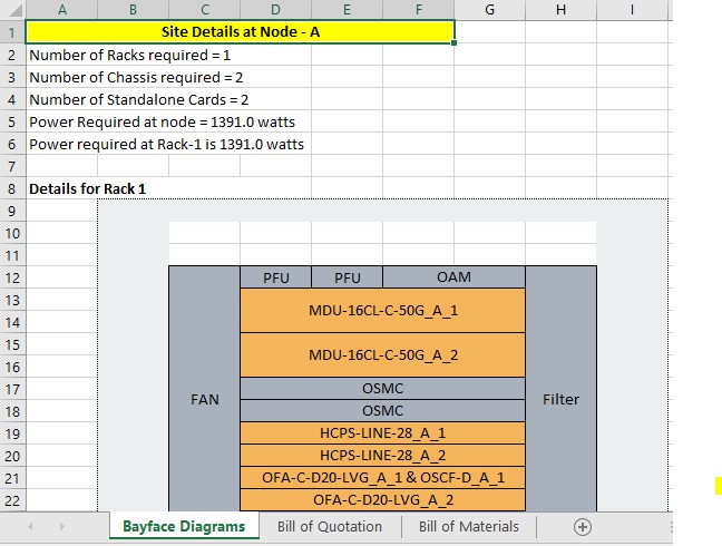
1. Bayface Diagram sheet: Based on the cards in the input BOM, the tool populates the nodewise bayface diagram of a network.
Figure 93:  Bayface diagram excel sheet
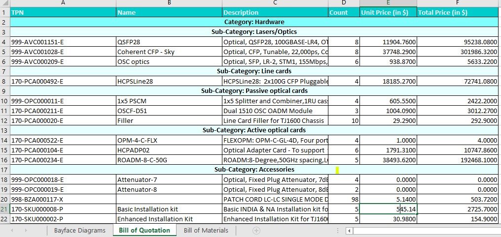
2. Bill of Quotation: Based on the cards in the input BOM, the tool populate the chassis and required commons in the BOQ sheet similar to the ones in the output file. Following are the 6 columns of the excel sheet:
— TPN: TPN of the device used in network design
— Name: Name of the device used in network design
— Description: Simple description of the device
— Count: Total count of the T PN used in the network design
— Unit Price: Price per each TPN
— Total Price: Total price per each TPN
Figure 94:  Bill of quotation excel sheet
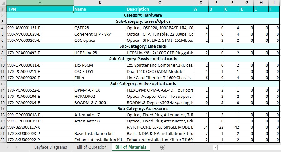
3. Bill of Materials sheet: Based on the cards in the input BOM, the tool output the updated BOM similar to the ones in the output file. Following are the columns of BOM output sheet:
— TPN: TPN of the device used in network design
— Name: Name of the device used in network design
— Description: Simple description of the device
— TPN Count: T PN count corresponding to the node used in the net work design. The number Nodes depends on the network. There will be one column for each node with node name as column heading
Figure 95:  Bill of materials excel sheet
11.3 OMS to path conversion tool
Click Tools option menu to view the list of drop-down options and click OMS to Path Conversion Tool from the options list.
Figure 96:  Page showing list of OMS to path conversion results
This section describes available button in OMS to path conversion tool page. Following is the button available:
Add New Network: Click Add New Network button which is available at top-right corner to perform OMS to Path conversion of a network.
11.3.2 Showing list of active OMS to path conversion tool results
This section describes table showing list of OMS to path conversion tool results. Following are the columns:
• Sl No: Serial number is used to enumerate the list of OMS to path conversion results
• Network Name: Displays the name of the network
• Time Stamp: Displays the time stamp of the network
• Actions: This column has maximum one button as listed below
— Download: Click Download button to download the OMS to path conversion tool in excel format.
11.3.3 OMS to path conversion procedure
This section describes how to perform OMS to path conversion of a network.
Follow the steps to convert OMS to path conversion network:
1. Click Add New Network button which is at the top-right corner. After clicking on the button a new form as opens up.
2. Following are the form parameters:
— Name of the Network: Provide name for the network
Brief Description: Provide a small description of the network. This field is optional.
Network Data in Excel File: Allows the user to import OMS details using excel file. Only excel document with file extension .xlsx is supported. Click Choose File button and browse into your system.Select the input excel sheet to upload the network topology along with OMS details.
3. Fill the form and click Submit to save data.
4. Each excel file should have four sheets
5. Following is the structure of excel file.
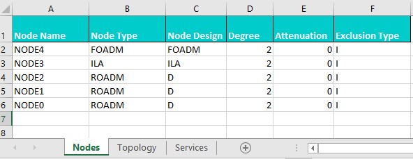
» Sheet one with name Nodes: This sheet lists all the nodes and their respective design criteria within the network. This sheet has 6 columns.
» Sheet two with name Topology: This sheet describes the network in the form of links or connections between the nodes listed in the Nodes sheet. This sheet has 14 columns.
» Sheet three with name Services: This sheet lists all the services flowing within the network. This sheet has 20 columns. This sheet is similar to the service sheet of network topolpgy except in the place of Paths column Subnet combination details needs to be provided by the user.
» Sheet four with name OMS: This sheet contains list of OMS which provides details of how services flows within the network. This sheet has 3 columns
NOTE: Ensure all the four sheets are present in the input excel file.
11.3.4 OMS to path conversion tool result in excel format
This section describes OMS to path conversion tool result in excel format. Following are the excel sheets of OMS to path conversion tool results:
1. Nodes: This sheet lists all the nodes and their respective design criteria within the network. This sheet has six columns. This sheet is same as Nodes sheet of input excel.
Figure 97:  Nodes sheet of input excel sheet
2. Topology: This sheet describes the network in the form of links or connections between the nodes listed in the Nodes sheet. This sheet has 14 columns. This sheet is same as Topology sheet of input excel.
Figure 98:  Topology sheet of input excel sheet
3. Services: This sheet contains list of all services flowing within the network. This sheet has 20 columns
Figure 99:  Service sheet of input excel sheet
NOTE: The BOM to Bayface Tool and OMS to Path conversion Tool sample excel sheets are present under the Documentation tab of APT tool.