![]()
![]()
![]()
|
|
|
|
OSMC01 (Optical Shelf Management Controller) performs Optical Supervisory Channel (OSC) processing up to 100Mbps, control path processing and timing functions.
OSMC01 card has a processor complex to perform APS/IBC route communication/Node management and other miscellaneous functions required for the system.
OSMC01 card supports the following functional features:
NOTE: Point number 4, 5, and 6 are not supported for this release.
The key functions of OSMC01 card are as follows:
NOTE: Synchronization Function is not supported.
Front panel
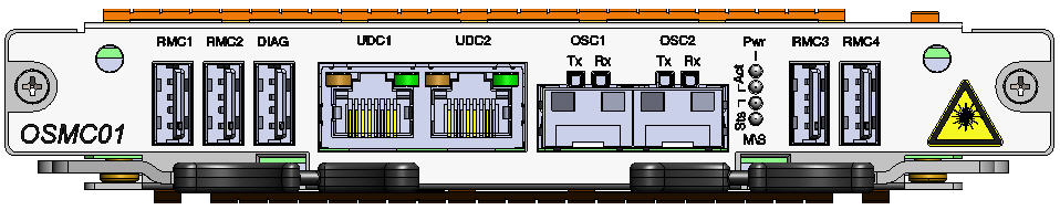
The following figure shows the front panel diagram of OSMC01 card supported in TJ1600-6 chassis without the mechanical adapter:
DIAG interface
The DIAG interface is a USB connector provided on the front panel of the OSMC01 card. This interface offers a serial connection to node using which a user can launch a terminal session to log onto the Operating System.
NOTE: The diagnostic interface is meant for use by authorized Tejas Networks personnel only.
OSC interface
Optical Supervisory Channel (OSC) interface receives the management information from the Optical supervisory channel filter, on the DWDM transmission path, primarily at the Intermediate Line Amplifier (ILA) sites.
OSC carries the management information related to the DWDM channels and enable to detect the fiber cuts and/or transmission degradation in the DWDM trunk. Typical wavelengths used for supervisory channel are 1490nm and 1510 nm which are well outside the C-band DWDM transmission.
Two SFP interfaces (OSC1 and OSC2) are provided for processing the OSC information from east and west directions which can cater up to 44dB of loss in the standard optical fiber.
Timing interface
OSMC is the timing master for SDH/1588 V2 timing schemes.
NOTE: Timing interface is not supported for this release.
Power specifications
OSMC01 - Power specification
Specification |
Range |
|---|---|
Input Voltage |
-48V DC |
Power consumption |
60W |
Visual indicator details
The visual indicators on the OSMC01 card has two LEDs - the Sts (Status) LED indicate the status of the card and the Act (Active) LED indicates whether the card is active or not.
OSMC01 - Active and status LEDs indications
Card State |
Status LED (Sts) |
Active LED (Act) |
|---|---|---|
Card initialization: State before the card initialize is complete on card insertion. |
Amber (Steady) |
Amber (Steady) |
Card in service: Initialization complete and card in service. |
Green (Steady) |
Green (Steady) |
Card mis-match: Node has already configured the slot with some other card. |
Amber |
Amber |
Card fails during boot up. |
Red |
Amber |
Card failed while in-service. |
Red |
Green |
Improper jack in of the card. |
Green (Blinking) |
Green (Blinking) |
Hard Reset: All devices reset, FPGAs cleared and reprogrammed. Goes to initializing state next. |
Amber |
Amber |
Soft Reset: Software is restarted, devices are reinitialized with provisioning. Goes to initializing state next. |
Green |
Green |
Early Ejector LED status: Both the ejectors are removed. |
Amber |
Off |
Early Ejector LED status: One ejector is removed (either left or right). |
Green |
Green |