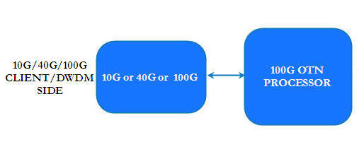
Two 40G/OTU3 optical ports, and one pluggable 100G/OTU4 optical port. It supports a maximum of 100G SDH/OTN backhaul. The card can be configured as transponder (at 10G) or muxponder (at 100G line side) card. The 100G port P1 supports Coherent DWDM CFP and non-coherent CFP. The 40G ports P2 and P3 are of QSFP+ types. The 10G ports P4 to P13 are of SFP+ types.
HCPSLine12 card supports CFP (P1), 2xQSFP+ (P2 and P3), 10xSFP+ (P4 to P13) interfaces.
The mode(s) supported includes:
NOTE 1: The 40G/OTU3 ports P2 and P3 are not supported in this product release.
NOTE 2: HCPSLine12 card can only be configured in muxponder mode in this product release. On the Node WUI, the card can be configured in 10x10G TO 1xOTU4 MUXPONDER mode.
Following figure shows the front panel view of HCPSLine12 card:

Power specifications- HCPSLine12
Specification |
Range |
|---|---|
Input Voltage |
-48 V |
Maximum Power consumption |
120 W |
The visual indicators on the HCPSLine12 card include two LEDs, the Active and the Status LEDs.
Possible LED status and their significance- HCPSLine12
Card State |
Status LED |
Active LED |
|---|---|---|
Card initialization: State before the card initialize is complete on card insertion |
Amber (Steady) |
Amber (Steady) |
Card in service: Initialization complete and card in service |
Green (Steady) |
Green (Steady) |
Card mis-match: Network Element has already configured the slot with some other card |
Amber |
Amber |
Card failed during boot up |
Red |
Amber |
Card failed while in-service |
Red |
Green |
Improper jack in of the card |
Green (Blinking) |
Green (Blinking) |
Hard Reset: All devices reset, FPGAs cleared and reprogrammed. Goes to initializing state next |
Amber |
Amber |
Soft Reset: Software is restarted, devices are reinitialized with provisioning. Goes to initializing state next |
Green |
Green |
Early Ejector LED status: One ejector is removed (contains one ejector switch in right) |
OFF |
Amber |
CFP Port Transmitter (Tx) and Receiver (Rx) LED Status- HCPSLine12
State |
Rx LED |
Tx LED |
|---|---|---|
CFP present (Laser on) with Rx LOS |
Amber |
Green |
CFP present (Laser off) with Rx LOS |
Amber |
Off |
CFP present (Laser on) with no Rx LOS |
Green |
Green |
CFP present (Laser off) with no Rx LOS |
Green |
Off |
Card failed while in-service |
Red |
Green |
CFP missing (LOS detected), Laser On (attempted) |
Amber |
Green |
CFP missing (LOS masked since XFP missing and set to Admin_down), Laser Off (attempted) |
Amber |
Off |
CFP failed (whether provisioned, unprovisioned, LOS or no LOS) |
Red |
Red |
SFP+ Port Transmitter (Tx) and Receiver (Rx) LED Status- HCPSLine12
State |
Rx LED |
Tx LED |
|---|---|---|
SFP+/QSFP+ present (Laser on) with Rx LOS |
Amber |
Green |
SFP+/QSFP+ present (Laser off) with Rx LOS |
Amber |
Off |
SFP+/QSFP+ present (Laser on) with no Rx LOS |
Green |
Green |
SFP+/QSFP+ present (Laser off) with no Rx LOS |
Green |
Off |
Card failed while in-service |
Red |
Green |
SFP+/QSFP+ missing (LOS detected), Laser On (attempted) |
Amber |
Green |
SFP+/QSFP+ missing (LOS masked since SFP missing and set to Admin_down), Laser Off (attempted) |
Amber |
Off |
SFP+/QSFP+ failed (whether provisioned, unprovisioned, LOS or no LOS) |
Red |
Red |
Supported Laser Types- HCPSLine12
Optics |
Rate |
Reach (Km)* |
|---|---|---|
10GE SFP+ |
10Gbps |
10 km |
S64.2b SFP+ |
STM-64 |
40 km |
P1L1-2D2 SFP+ |
STM-64/OTU2 |
80 km |
DWDM Fixed/Tunable SFP+ |
10Gbps/STM-64/OTU2 |
80 km |
QSFP+ |
40GE/OTU3 |
10 km |
CFP |
100GBASE-SR10/OTU4 |
100m |
CFP |
100GBASE-LR4/OTU4 |
10 km |
CFP |
100GBASE-ER4/OTU4 |
40 km |
CFP Coherent |
100GE/OTU4 |
80 km |
CFP Coherent |
100GE/OTU4 |
~1000 km (amplified) |
* For G.652 fiber under Standard link conditions |
||
HCPSLine12 card supports the following functional features:
Following is a schematic of the traffic configuration with POTP configuration:

The HCPSLine12 card also supports 10G and 40G Client to 1xOTU4 muxponder configurations as described earlier. The client side supports SFP+/QSFP+ optical interface and the line/network side supports CFP.
Following functionalities in particular are supported:
Following is a schematic of the traffic configuration in DWDM configuration:

Optical interface specifications for CFP_client side
Specifications |
100GBase-SR10/OTU4 (100m) |
100GBase-LR4/OTU4 (10km) |
100GBase-ER4/OTU4 (40km) |
|---|---|---|---|
Minimum Output Power |
-7.6 dBm |
3.5 dBm |
3.3 dBm |
Maximum Output Power |
2.4 dBm |
8.9 dBm |
8.9 dBm |
Receiver Sensitivity |
-9.4 dBm |
-10.3 dBm |
-23.2 dBm |
Receiver Overload |
-2.4 dBm |
8.9 dBm |
10.5 dBm |
Wavelength (nominal) |
850 nm |
1294 to 1310 nm |
1294 to 1310 nm |
Connector Type |
MPO24 |
LC |
LC |
Fiber Type |
Multi Mode |
Single Mode |
Single Mode |
100G DWDM_CFP Optical interface
Specifications |
CFP Coherent Metro DWDM |
CFP Coherent ZR (80Km) |
|---|---|---|
Data Rate |
103.6Gbps-120Gbps |
103.6Gbps-120Gbps |
Minimum Output Power |
-15 dBm |
-15 dBm |
Maximum Output Power |
+1 dBm |
+5 dBm |
Receiver Sensitivity |
-18 dBm |
-20 dBm |
Receiver Overload |
0 dBm |
+5 dBm |
Wavelength |
1528 to 1569nm at 50GHz Tuning |
1528 to 1569nm at 50GHz Tuning |
OSNR for BER 10e-15, optimized receiver threshold |
14dB with SD-FEC |
22.5dB with SD-FEC |
Chromatic dispersion tolerance |
± 22000ps/nm |
± 2500ps/nm |
Connector Type |
LC |
LC |
Fiber Type |
Single Mode |
Single Mode |