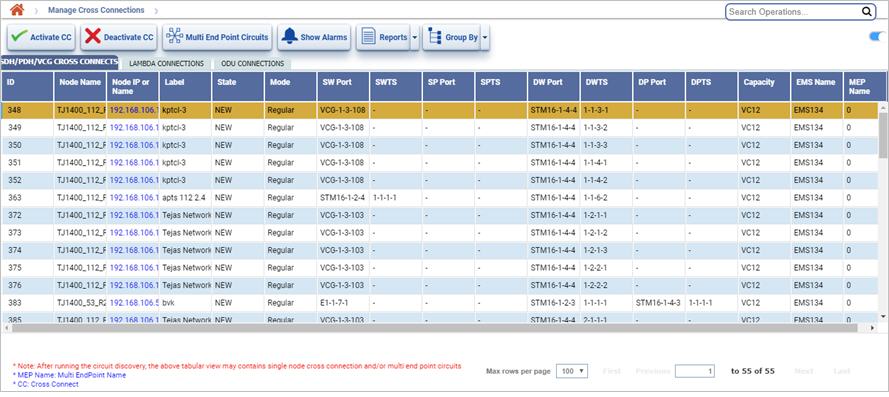
To view the Manage Cross Connections page, do one of the following steps:

NOTE: After running the circuit discovery, the Manage Cross Connections page may display single node cross connection and/or multi end point circuits.
Manage Cross Connections button
Button |
Description |
|---|---|
|
Activate CC button allows you to activate the cross connect(s) that are in pending or partial state. This feature is not supported for this release. |
|
Deactivate CC button allows you to deactivate the selected cross connect(s). |
|
Multi End Point Circuits button allows you to click and open the multi end point circuits page. |
|
Show Alarms button allows you to view alarms for the selected cross connect. |
|
Summary Report button allows you to click and export the data to any of the four formats: PDF, CSV, XML, and HTML. |
|
Group Options button allows you to click and group the cross connects by the criteria selected. |
Manage Cross Connections parameters
Attribute |
Description |
|---|---|
SDH/PDH/VCG CROSS CONNECTS/ LAMBDA/ODU CONNECTIONS |
|
ID |
Displays the ID assigned to the cross connect. |
Node Name |
Displays the name of the node. |
Node IP or Name |
Displays the IP address of the node. Also allows you to click the link to open that node on Manage Nodes page. |
Label |
Displays the label of the cross connect. |
State |
Displays the state of the cross connection. |
Mode |
Displays the mode of the cross connection. |
SW Port |
Displays the source port of the work path. |
Frequency |
Displays the frequency of lambda connections. |
SWTS |
Displays the source time slot of the work path. This parameter is not applicable for lambda connection. |
SP Port |
Displays the source port of the protect path. |
SPTS |
Displays the source time slot of the protect path. This parameter is not applicable for lambda connection. |
DW Port |
Displays the destination port of the work path. |
DWTS |
Displays the destination time slot of the work path. This parameter is not applicable for lambda connection. |
DP Port |
Displays the destination port of the protect path. |
DPTS |
Displays the destination time slot of the protect path. This parameter is not applicable for lambda connection. |
Capacity |
Displays the capacity of the cross connection. |
Ems Name |
Displays the name of the EMS. |
MEP Name |
Displays the name of the Maintenance End Points. |
Perform the following steps to search cross-connects based on the options displayed on Manage Cross Connections page:
Node/IP: To search cross-connects based on node enter the name of node in the text box. To search cross-connects based on the IP select the check box and enter the IP in the text box. On entering a character a list related to it is displayed and the user can select from the options.
Using Circuit option or the Manage Circuit page, you can view all the cross connections. You can perform the following operations from this page.

NOTE: The blue arrow mark in the graphical view indicates the endpoint if it is an PDH/VCG cross connect.
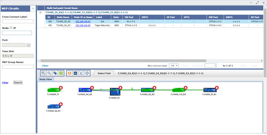
Multi End Point Circuits Parameters
Attribute |
Description |
|---|---|
ID |
Displays the ID assigned to the circuit. |
Node Name |
Displays the name of the node. |
Node IP or Name |
Displays the IP of the node. |
Label |
Displays the label of the node. |
State |
Displays the state of the cross connection. |
SW Port |
Displays the source port of the work path. |
SWTS |
Displays the source time slot of the work path. |
SP Port |
Displays the source port of the protect path. |
SPTS |
Displays the source time slot of the protect path. |
DW Port |
Displays the destination port of the work path. |
DWTS |
Displays the destination time slot of the work path. |
DP Port |
Displays the destination port of the protect path. |
DPTS |
Displays the destination time slot of the protect path. |
Capacity |
Displays the capacity of the cross connection. |
Ems Name |
Displays the name of the EMS. |
Icons of Multi End Point Circuits
Icon |
Description |
|---|---|
|
Allows you to zoom in the current view. |
|
Allows you to minimize the enlarged view. |
|
Allows you to restore the normal view. |
|
Allows you to refresh the current view for any updates. |
|
Allows you to view the alarms for the MEP circuit. |
|
Allows you to launch the node page for the selected node. |
|
Allows you to expand the graphical view to view the adjacent nodes. |
|
Allows you to create cross connects to edit the MEP into circuit. |
General Links of Multi End Point Circuits
Icon |
Description |
Clear |
Clears the MEP circuits displayed in the Multi End Point Circuits page. |
First |
Allows you to view the entries in the first window. |
Previous |
Allows you to view the entries in the previous window. |
Next |
Allows you to view the entries in the next window. |
Last |
Allows you to view the entries in the last window. |
NOTE: This feature is applicable only for debugging purpose and for missing of a single node/cross-connect/Topological link.
The filter MEP option provides a set of attributes on which the user can filter MEP attributes. To filter MEP circuit, do the following steps:
Filter MEP Circuit Parameters
Parameter |
Description |
|---|---|
Cross Connect Label |
Enter the label provided for the specific cross connect to be filtered. |
Node Name/IP Address |
Enter the Node name. If you want to enter the IP Address, select the checkbox and enter the IP Address. |
TP Name |
Termination Point: Select the desired port from the list displayed. Click >> to display the list. |
Time Slot |
Select the desired time slot from the list displayed. Click >> to display the list. |
MEP Group Name |
Enter the group name of the Maintenance End Point. |
To view the node and trunk tool tip details, do the following steps:
Node and Trunk Tool Tip Information for circuits
Parameter |
Description |
|---|---|
Node Tool Tip Information |
|
EMS |
Displays the name of the EMS. |
IP |
Displays the IP of the node. |
Product Name |
Displays the product name of the node. |
Alarms |
Displays the count of different severity alarms present on the node. |
NOTE: A warning message is displayed as "Cross connection is missing". |
|
Trunk Tool Tip Details |
|
Local Node Name |
Displays the name of the source node. |
Local Port |
Displays the shelf index, slot index, and port index of the source node indicating port capacity. |
Remote Node Name |
Displays the name of the node at the remote end. |
Remote Port |
Displays the shelf index, slot index, and port index at the remote end indicating port capacity. |
Node and Trunk Tool Tip Information for MEP circuits
Parameter |
Description |
|---|---|
Node Tool Tip Information |
|
EMS |
Displays the name of the EMS. |
IP |
Displays the IP of the node. |
Product Name |
Displays the product name of the node. |
Alarms |
Displays the count of different severity alarms present on the node. |
NOTE: A message is displayed as "Cross Connection is Present". |
|
Trunk Tool Tip Details |
|
Local Node Name |
Displays the name of the source node. |
Local Port |
Displays the shelf index, slot index, and port index of the source node indicating port capacity. |
Local Timeslot |
Displays the timeslot of the local node. |
Remote Node Name |
Displays the name of the node at the remote end. |
Remote Port |
Displays the shelf index, slot index, and port index at the remote end indicating port capacity. |
Remote Timeslot |
Displays the timeslot of the remote node. |
NOTE: A message is displayed as "This Trunk has MEP Path". |
|
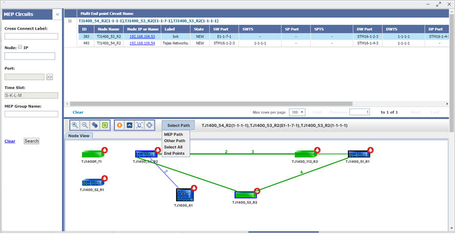
To view the different paths, do the following steps:

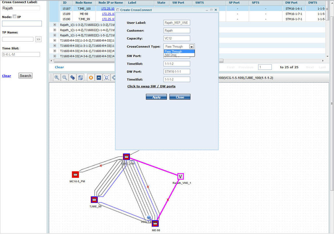
To edit MEP, do the following steps:

If node was pass-through, select the cross-connect type as Pass Through.
If node was source or destination, select the cross connect type as Add Drop.