Previous Topic

Next Topic

Book Contents

Add switch to a Hub and Spoke MPLS service

Perform the following steps to add a node/switch to a hub and spokes ELAN service in MPLS domain:
  1. Go to Configuration > Layer 2 > Services menu and click Complete Services option. The Complete Services page is displayed.
  2. Search and select the hub and spoke service desired to modify. Double-click that service. A detailed page of the service is displayed.
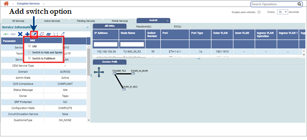
  3. Under Service Information column, click (Add) and select Switch to Hub and Spoke option.

    Add switch option and in Hub & Spokes Service

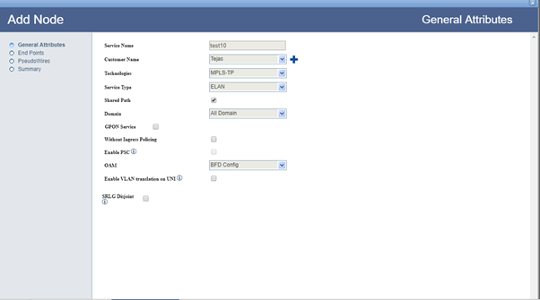
  4. On Add Node- General Attributes window displayed, select the Allow CIR Traffic in ELAN check box (if desired) and click Next End Points page is displayed.

  5. To add end point, click Add.
  6. Select the node desired to add by performing one of the action:
  7. For chosen node, select the check box against the port followed by entering the VLAN value for Regular mode or select the check box under All column for Transparent mode.

    If the service is in Qos domain, associate a Priority Mapping Profile or DSCP Mapping Profile or a pair of TCProfile and COS value.
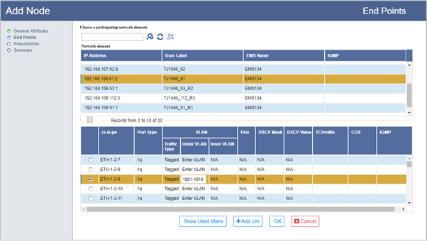
    Add Switch- Adding End Points

  8. Click Add Uni > OK. The endpoint and UNI gets added. Click Add Uni to add another UNI on same node, if desired. But only one node is allowed to be added.
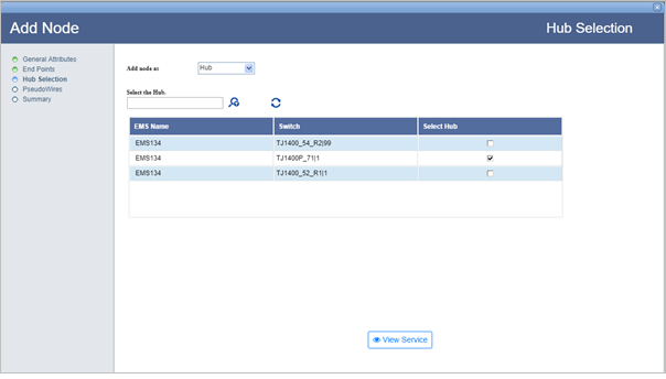
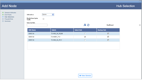
  9. Click Next. The Hub Selection page is displayed.
  10. Do one of the following:
  11. Click View Service to display the existing service path. Click Back to return to the Hub Selection page.
  12. Click Next. PseudoWires page is displayed.

    To find path for the pseudowire automatically,
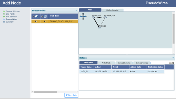
    1. Enable Find Path button by selecting Auto Path Icon (Auto Path) check box and then select check box against the added end points. Check boxes will be selected by default.
    2. Click Find Path. A success message is displayed. Path is found successfully.
    3. Click OK and select the pseudowire endpoint (Sw1--Sw2). Graphical representation of the pseudowire detected automatically is displayed under the View tab as shown in the following figure. Details of work path, protect path, excluded switches and excluded tunnels is available under Details:

      Add Switch (PseudoWires- Auto Path)

      NOTE: When finding the pseudowire path automatically, the user is provided an option to exclude switches/tunnels. Select Excluded Switches and Excluded Tunnels tab. Click Add button and select the desired nodes and/links. Click Exclude Nodes or Exclude Links followed by Done. Remove button can be used to delete the added data. Select Find Path. Pseudowire path is calculated once again, excluding the selected switches/tunnels in the path.

    To find path for the pseudowire manually,

    a. Uncheck Auto Path Icon (Auto Path) check box and then select the added end points. Click Manual Path button displayed under the View tab. Topology view is displayed.

    b. Select a path/link between the two selected end points (highlighted in black) and click Add Work.

    c. If protection was selected, select another link between the end points and click Add Protect.
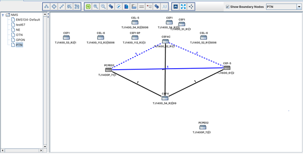
    1. Click Done. A graphical representation of the pseudowire added is displayed on the PseudoWires page under View tab along with work and protect path information under Details column.

      Add Switch (PseudoWires- Manual Path)

  13. Click Next. Summary page is displayed.

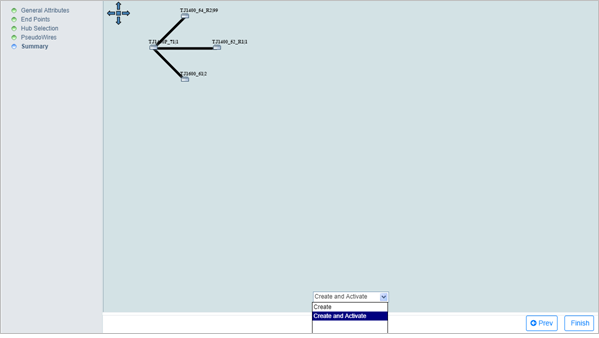
    Add switch (Summary)

  14. From the drop down menu, select Create to create the service or Create and Activate to create and activate the service as desired.
  15. Click Finish. Node added successfully message is displayed.
  16. Click OK.

See also

Create ELAN services with Hub and Spoke