![]()
![]()
![]()
![]()
|
|
|
|
|
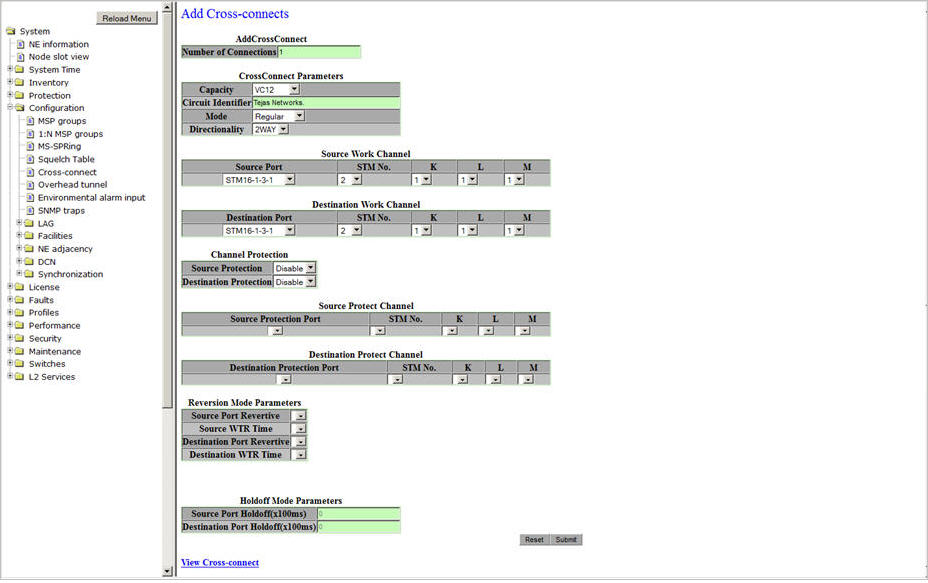
Perform the steps given below to add cross-connects.
If the value for Number of Connections parameter is >1, then a message "This operation will create <Number of Connections> connections with contiguous time slots. Are you sure you want to continue ?" is displayed. Click OK to continue. A Summary of the cross-connects created is displayed. The procedure is completed.
View Cross-connect link will direct you to the Configure Cross-connects preview pane.
Add Cross-connect link will direct you to the Add Cross-connects preview pane.
Add Cross-connects parameters
Parameter |
Description |
Default Value |
Acceptable Value |
|---|---|---|---|
AddCrossConnect |
|||
Number of Connections |
Enter the number of cross-connects desired to create. |
1 |
Up to 672 at a time |
CrossConnect Parameters |
|||
Capacity |
Select the capacity for the cross-connect. NOTE: If the cross-connect Capacity is changed after setting a value for 'Number of Connections' parameter, the Number of Connections will revert to the value 1. |
VC12 |
|
Circuit Identifier |
Enter a name for the cross-connect. |
Tejas Networks |
Up to 40 alphanumeric and special characters |
Mode |
Select the cross-connect mode. |
Regular |
|
Directionality |
Select the direction of the data flow in the cross-connect. |
2WAY |
|
Source Work Channel/ Destination Work Channel |
|||
Source Port/ Destination Port |
Allows you to select the source/destination port for the work channel. |
The first STM port configured |
List of available STMn and PDH ports |
STM No. |
Allows you to select the STM number at the source/destination port for the work channel. The values available in drop down option depends on the capacity of the work port selected. |
1 |
|
K |
K specifies TUG3. |
1 |
1 to 3 |
L |
L specifies TUG2. |
1 |
1 to 7 |
M |
M specifies VC number of the cross-connect. |
1 |
|
Channel Protection |
|||
Source Protection/ Destination Protection |
Allows you to enable or disable protection for source/destination port of work channel.
|
Disable |
|
Source Protect Channel/ Destination Protect Channel: The parameters under this field are editable when channel protection is set as enable at source and/or destination work channel. |
|||
Source Protection Port/ Destination Protection Port |
Allows you to select the source/destination port for the protection channel. |
-- |
List of available STMn and PDH ports |
STM No. |
Allows you to select the STM number at the source/destination for the protection channel. The values available in drop down option depends on the capacity of the protection port selected. |
1 |
|
K |
K specifies TUG3. |
1 |
1 to 3 |
L |
L specifies TUG2. |
1 |
1 to 7 |
M |
M specifies VC number of the cross-connect. |
1 |
|
Reversion Mode Parameters: The parameters under this field are editable when channel protection is set as enable at source and/or destination work channel. |
|||
Source Port Revertive/ Destination Port Revertive |
The reversion mode of the protection at source/destination.
|
Non-revertive |
|
Source WTR Time/ Destination WTR Time |
For Revertive mode, allows you to select the time in minutes after which the traffic will be reverted to the work path after failure clears at source/destination on the work path. |
5 |
1 to 12 minutes |
Holdoff Mode Parameters |
|||
Source Port Holdoff (x100ms) |
Defines the wait time for reporting the alarms in the interconnected rings when failure condition exists on the source port. This field is not editable if source protection is set as disable. |
0 |
0 to 100 |
Destination Port Holdoff (x100ms) |
Defines the wait time for reporting the alarms in the interconnected rings when failure condition exists on the destination port. This field is not editable if destination protection is set as disable. |
0 |
0 to 100 |
View Cross-connect |
A click on the link will direct you to the Configure Cross-connects preview pane. |
||