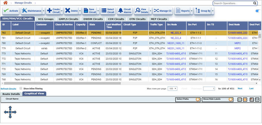
To view the circuits, click Configuration > Layer 1 > Manage Circuits. The Manage Circuits page is displayed. It displays the list of all circuits created and discovered from TJ5500 in different tabs based on the circuit type.
Figure given below shows Manage Circuits page with SDH/PDH/VCG Circuits tab selected.

Manage Circuits buttons
Button |
Description |
|---|---|
|
Click Activate button to activate the circuits that are in pending or partial state. |
|
Click on Maintenance button and click Toggle LoopBack to toggle the loopback. |
|
Click Create Circuit button to create a new circuit and select from the options. |
|
Click Delete button to delete and/or deactivate the circuit.
|
|
Click Save Circuit button and select the following:
|
|
Click Select Circuits For Circuit provisioning button to select the circuits for circuit provisioning over it. |
|
Click Circuit Alarms button to view the alarms raised on the selected circuit. |
|
Click View Details button and select the following to view circuit details.
|
|
Click Manage CC button to open the Manage Cross Connections page directly. |
|
Click Reports button and select the desired option to export the data to any of the four available formats namely PDF, CSV, XML, HTML. |
|
Click Group By button to group the data based on the parameters provided in the drop down. |
Manage Circuit parameters
Attribute |
Description |
|---|---|
SDH/PDH/VCG Circuits/ VCG Groups/ GMPLS Circuits/ DWDM Circuits/ CEM Circuits/ OTN Circuits/MEP Circuits |
|
ID |
Displays the circuit identifier. |
Label |
Displays the name of the circuit. |
Customer |
Displays the name of the customer. |
Class of Service |
Displays the type of protection configured on the circuit. |
Call ID |
Displays the call ID. This parameter is displayed only for GMPLS circuits. |
Capacity |
Displays the circuit capacity. |
State |
Displays the circuit state. |
Last Modified Time |
Displays the time, the circuit was last modified. |
Circuit Type |
Displays the type of circuit as 'P2P' or 'Singleton'. |
Traffic Type |
Displays the type of traffic carried by the circuit. |
Frequency |
Displays the frequency. It is displayed only for DWDM circuits. |
Direction |
Displays the direction of port connect. It is displayed only for DWDM circuits and MEP circuits. |
Src Node |
Displays the source node of the circuit. |
Src Port |
Displays the source port of the circuit. |
Src TS |
Displays time slot of the source port of the node. |
Dest Node |
Displays the destination node of the circuit. |
Dest Port |
Displays the destination port of the node. |
Dest TS |
Displays time slot of the time slot of the port. |
HO |
Select this option to know whether the circuit is high order circuit or not. |
PM Granularity |
Displays for which granularity the PM is enabled. This interval can be either 15minutes or 24hours or both. |
PM Collection Nodes |
Displays the PM of the collection of the nodes. |
PM Enabling Time |
Displays the interval where the PM is enabled. |
Auto Planned |
Displays the auto planned circuits. |
Protect Continue |
Select this option to protect and continue. |
Auto Rerouted |
Select the option to auto reroute the circuits. |
Revertive |
Select this when the Traffic is switched back to the work tunnel after the WTR expiration. |
WTR(min) |
This field is enabled when the Revertive mode is selected. Maximum acceptable value: 12 minutes. |
Disjointness |
Disjointness is to ensure no element is common to mitigate the risks. It is supported in 1_1_R and 1_1_F class of services in GMPLS circuits. Select the option from following:
|
Disjointness Degree |
Disjointness degree is parameter to allow load sharing on the links. This parameter is applicable for GMPLS circuits.
|
Priority |
Displays the priority assigned to the circuit if multiple services are traversing on the link. Highest priority is 0 and lowest is 7. On fiber cut, highest priority services are rerouted first. This parameter is applicable for GMPLS circuits. |
Maintenance Mode |
Displays the maintenance mode. |
User Remark |
Displays the remark made by the user. |
CST |
The check box is enabled for those circuits on which Client signal termination (CST) is configured and is disabled if CST is not configured. |
CEM |
The check box is enabled for those circuits on which Circuit emulation (CEM) is configured and is disabled if CEM is not configured. |
PM Enabled Ports |
|
Additional tabs and buttons |
|
Refresh Circuits |
This button is provided at the bottom left of page to refresh the Manage Circuits page. |
Show inline filtering |
Select the check box provided to enable filtering option at each attribute. |
Route Details |
Click on this tab provided at the bottom left of page to view the complete routing details of the circuit. |
PGP Details |
Displays the details of Port group protection. |
Graphical View |
Displays the graphical view of the selected circuit. |
Filter options
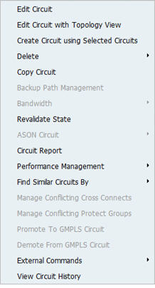
On Manage Circuits page right click on the circuit. The actions that can be performed on the circuit are displayed.
NOTE: Only the highlighted actions can be performed on the circuit and the disabled (gray color) actions cannot be performed.

NOTE: Revalidate State is used as a work around for updating the state of the circuit.
Similar circuits are searched by matching the routes.