Previous Topic

Next Topic

Book Contents

Draw a network topology

This section describes the procedure to draw the network topology. Following are the steps to draw a network:

  1. To draw a network, click on Draw New Network which is at the top-right corner. After clicking the button, a canvas opens up with various options for drawing the network.
  2. In order to create a topology, select the type of node and place it on the canvas. To select the type of node:
    1. Click on one of the node types (viz. ROADM, FOADM, GTN and ILA) present on the left side of the canvas with left mouse button.
    2. While continuing to press the left mouse button, drag the selected node on to the canvas.
    3. Once the node is positioned at the appropriate place on the canvas, release the left mouse button. Application will automatically assign default name to the node.
  3. Once the node is placed on the canvas, to view the node details hover the mouse on the node; a pop-up appears showing details about the node. The pop-up displays the following information:

    For example: ROADM or FOADM or GTN or ILA

    For example: Directional (A) or Directionless (D) or Colorless Directionless (CD) or Colorless Directionless Contentionless (CDC) or

    Fixed-Optical-Add-Drop-Multiplexer (FOADM) or Colorless Directional (CA) and ILA.
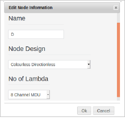
  4. To edit an already placed node, click on the node with the left mouse button. Once clicked, the node color changes to red and the pop-up form to edit the node information appears. Following are the available parameters within the form:

    Pop-up form to edit node information

    1. Name: Provides an option to edit the node name.
    2. Node Design: Provides an option to edit the node design, for example: Directional (A) or Directionless (D) or Colorless Directionless (CD) or Colorless Directionless Contentionless (CDC) or Fixed-Optical-Add-Drop-Multiplexer (FOADM) or Colorless Directional (CA) or ILA.
  5. Once the nodes are placed, connect the nodes with edges. To add an edge, there should be minimum two nodes. There is also an option to add multiple edges simultaneously, instead of one at a time. To add a single edge between the two nodes following are the steps:
    1. Click on Add Edge, present on the top of the canvas.
    2. Click on the node which is present on the canvas using the left mouse button.
    3. While continuing to press the left mouse button, drag the mouse pointer to another node that you wish to connect.
    4. Once the pointer reaches the other node, release the left mouse button. This action of click-drag-release will create an edge connecting the two nodes. Now the edge or link is established between the two nodes.
    5. To connect any two nodes, you have to perform this action repeatedly. However, there is also an option to quickly connect multiple pair of nodes as described later.

    Hover the cursor on the established edge between the nodes; a pop up appears.

    The pop-up will display the following information:

    - Link Name: Displays name of link.

    - Distance (km): Displays distance between the nodes in kilometers.

    - Fiber Type: Displays the type of the fiber, for example: G.652, G.653, G.654, G.655-TW and G.655-LEAF.

    - Fiber Loss (dB): Measured loss between nodes in decibels (dB).

    To edit the edge or link, double click on the edge using left mouse button; a pop-up form appears to edit the edge information.
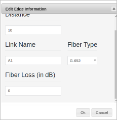
    Pop-up form to edit edge information

    Following are the available parameters within the form:

    - Link Name: Provides an option to edit a link name.

    - Distance (km): Provides an option to edit distance between the nodes in kilometers.

    - Fiber Type: Provides an option to edit type of the fiber, for example: G.652, G.653, G.654, G.655-TW and G.655-LEAF.

    - Fiber Loss (dB): Provides an option to edit loss between nodes in dB.

  6. To add multiple edges between the two nodes:
    1. Click on the Add Edges which is present on the left side of the screen.
    2. Click on the node which is present on the canvas using the left mouse button, and drag the edge or link to another node present on the canvas.
    3. To add multiple edges between the nodes repeat the above process. Then the edge or link is established between the two nodes.

      The pop-up will display the following information:

      - Link Name: Displays link name.

      - Distance (km): Displays distance between the nodes in kilometers.

      - Fiber Type: Displays the type of the fiber, for example: G.652, G.653, G.654, G.655-TW and G.655-LEAF.

      - Loss (dB): Measured loss between nodes in dB.

  7. To edit the edge or link between nodes:
    1. Double click on the edge using left mouse button of the mouse
    2. A pop-up form appears to edit the edge information.

    Following are the available parameters of edit edge information form:

    - Link Name: Provides an option to edit a link name.

    - Distance (km): Provides an option to edit distance between the nodes in kilometers.

    - Fiber Type: Provides an option to edit type of the fiber, for example: G.652, G.653, G.654, G.655-TW and G.655-LEAF.

    - Loss (dB): Provides an option to edit loss between nodes in dB.

  8. Once all the nodes and edges are added, to save the topology click on Save Topology button on the left-side of the canvas.

    NOTE: Services cannot be added using the canvas.

See also

Working with network topology

Accessing network topology

Available buttons

Showing list of active network topologies

Upload network topology

Download or export network topology

Delete network topology

Restore network topology

Duplicate network topology

Change the name of the network topology

View the network topology

Network topology management