![]()
![]()
![]()
|
|
|
|
Variable Optical Attenuator (VOA) is required in a DWDM network to adjust the power levels in order to control the transmission performance. VOA card supports eight ports in which eight hot pluggable VOA SFP modules can be inserted. VOA SFP modules can be either bright type or dark type and can be software configured to operate in constant attenuation or constant output power mode. Attenuation is minimum during power fault in the bright type VOA, and it is maximum during power fault in the dark type. VOA card covers C band wavelength range.
Each card is half slot and a total of two such cards can be used in one slot with an optical adapter card (HCPADP02) thereby supporting 16 VOA SFP modules per slot.
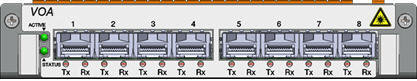
Front panel
The following figure shows the front panel diagram of the VOA card.
Power specifications
VOA - Power specifications
Specification |
Range |
|---|---|
Input Voltage |
-48V DC |
Maximum Power Consumption |
6 W |
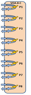
Functional diagram
Visual indicator details
The visual indicators on the VOA card has two LEDs - the Sts (Status) LED indicate the status of the card and the Act (Active) LED indicates whether the card is active or not.
VOA - Active and status LEDs indications
Card State |
Status LED |
Active LED |
Card initialization: State before the card initialize is complete on card insertion. |
Amber (Steady) |
Amber (Steady) |
Card in service: Initialization complete and card in service. |
Green (Steady) |
Green (Steady) |
Card mis-match: Network Element has already configured the slot with some other card. |
Amber |
Amber |
Card failed during boot up. |
Red |
Amber |
Card failed while in-service. |
Red |
Green |
Improper jack in of the card. |
Green (Blinking) |
Green (Blinking) |
Hard Reset: All devices reset, FPGAs cleared and reprogrammed. Goes to initializing state next. |
Amber |
Amber |
Soft Reset: Software is restarted, devices are reinitialized with provisioning. Goes to initializing state next. |
Green |
Green |
VOA - SFP Port LEDs indications
State |
Rx LED |
Tx LED |
SFP present with LOS. |
Amber |
Amber |
SFP present (Tx enabled) with no Rx LOS. |
Green |
Green |
SFP present (Tx disabled) with no Rx LOS. |
Green |
Amber |
Card failed while in-service. |
Red |
Red |
SFP missing |
Amber |
Off |
SFP failed (whether provisioned, unprovisioned, LOS or no LOS). |
Red |
Red |
NOTE: For proper LED indication, wait for at least 30 seconds before and after connecting fiber to the SFP interface on the VOA card.
Typical specifications and functionalities of the VOA card are as follows:
The following table summarizes the different parameters and its typical values:
Typical specifications of VOA card
Parameter |
Units |
Specification |
||
Minimum |
Typical |
Maximum |
||
Minimum channel spacing |
GHz |
50 |
100 |
-- |
Spectral range |
nm |
1528 |
-- |
1565 |
Insertion loss |
dB |
-- |
-- |
2.5 |
Attenuation range |
dB |
0 |
-- |
20 |
Input power range |
dBm |
-10 |
-- |
+21 |
VOA Type |
-- |
Bright/Dark |
Dark |
|
Block Attenuation Loss |
dB |
35 (for Dark Type) |
||
Return loss |
dB |
<-40 |
||
Attenuation accuracy |
dB |
-- |
-- |
+/-1.0 |
Polarization dependent loss |
dB |
-- |
-- |
0.3 |
Power consumption per module |
mW |
-- |
-- |
750 |