![]()
![]()
![]()
|
|
|
|
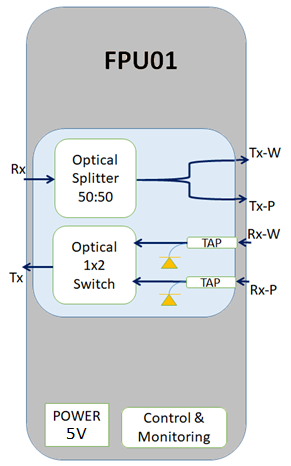
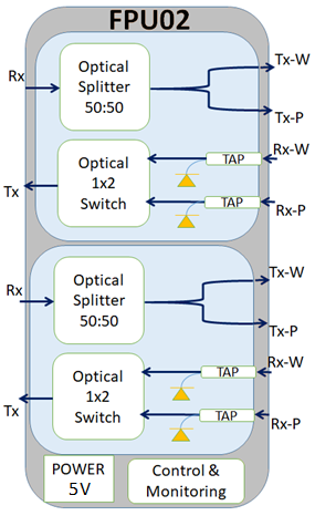
The main function of the fiber protection unit (FPU) is to protect against optical fiber line failures. The unit has a 50:50 (3dB) power splitter in the transmit direction and a 1x2 optical switch in the receive direction. The unit will switch to the protection path when it detects the loss of optical power or when the optical power is decreased below the set threshold. The main control interface to this module is I2C from the backplane. The protection switch can be configured as revertive, non-revertive and forced switching by the user.
FPU is available in two variants:
FPU01 module is supported with an optical adapter HCPADP01 in 1/3rd. And also supported in 2/3rd slot with mechanical adapter card FPUADP01.
FPU02 module is supported with an optical adapter HCPADP02 in 1/2 slots.
Following are the schematics of the FPU:
The Tx and Rx ports are connected to any optical interface which needs to be protected for optical fiber cut in the network side. The Tx-W and Tx-P are the work and protect transmit ports, respectively which need to be connected to the work and protect optical fibers. Similarly, Rx-W and Rx-P are the work and protect receive ports, respectively which need to be connected to the work and protect optical fibers.
Typical specifications
Typical specifications and functionalities of the FPU card are as follows:
FPU - Typical Specifications
Specification |
Range |
Specification |
||
Min |
Typical |
Max |
||
Spectral range |
nm |
1260~1360 & 1490~1610 |
||
Insertion Loss (Rx -> Tx_P or Tx_W) |
dB |
- |
3.5 |
- |
Insertion Loss (Rx_W or Rx_P-> Tx) |
dB |
- |
1.5 |
- |
Input power range to Rx_W or Rx_P) |
dBm |
-35 |
- |
+6 |
Absolute power measurement accuracy |
dB |
- |
- |
+/-0.5 |
Switching time |
ms |
- |
- |
<25 |
Power Handling |
mW |
- |
500 |
- |
Type of Connector |
LC/PC |
- |
- |
- |
Front panel
The following figure shows the front panel of FPU01 card with an adapter.

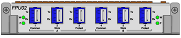
The following figure shows the front panel of FPU02 card.
Power specifications
FPU - Power specifications
Specification |
Range |
Input Voltage |
-48V DC |
Maximum Power consumption |
FPU01: 5W FPU02: 10W |
Visual indicator details
The visual indicator on FPU card includes port level LEDs which indicates status of work/protect port.
Port state |
Work LED status |
Protect LED status |
Signal fail on work and protect port. |
Red |
Red |
Signal fail on work and valid signal on protect and active path is Protect. |
Red |
Green |
Signal fail on protect valid signal on work and active path is work. |
Green |
Red |
Valid signal is present on work and protect, active path is Work. |
Green |
Amber |
Valid signal is present on work and protect, active path is Protect. |
Amber |
Green |