![]()
![]()
![]()
|
|
|
|
The Optical Fiber Monitoring (OFM) uses Optical Time Division Reflectometry (OTDR) to detect link degradation and faults over user-defined spans and thresholds. It returns high-resolution fault location measurements to the network operations center within minutes, which can be further analyzed to pin point exact fault location. This helps user to rectify network fault quickly and efficiently minimizing the network downtime. Featuring a powerful, easy to use configuration interface, the OFM unit can be deployed in a range of applications for in-building and access/metro fiber networks.
It can be housed in a standalone 1 RU 19’’ sub-rack. This unit is interfaced to Element Management Software (EMS) as standalone unit or integrated through the product using the RJ45 NMS port. Featuring a powerful, easy to use configuration interface. Standard OTDR trace file returned by the unit can be analyzed at any point of time offline using the interface.
OFM unit is used for monitoring dark fiber or live fiber carrying customer traffic. OFM inserts out-of-band OTDR signal at 1625nm into live fiber and performs real-time link measurement without affecting performance of live channels.
OFM unit has following key features:
OFM - Power specifications
Specification |
Range |
|---|---|
Input voltage |
-48 V to -60V |
Maximum power consumption |
20.5 W |
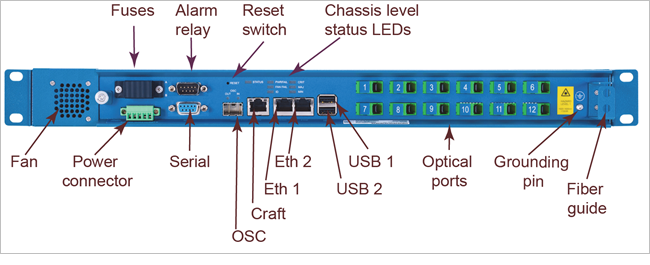
Alarm Relay port
The OFM supports three sets of two pin alarm relays: Critical, Major and Minor. These alarm relays can be configured to form a normally open, alarming on closed circuit. Access to the alarm relays is made through the DB9 Alarm relay on the front of the unit.
Serial port
Serial port uses DB9 female connector and supports RS-232 standard. This port is used for local access. It supports local configuration of the node’s IP address.
OSC port
The OSC SFP port supports both SFP and SFP+ pluggable modules with GbE and 100MbE data rates
Two LEDs on the SFP port indicate RX LOS and TX state.
NOTE: OSC port is not supported for this release.
Craft port
Serial craft port provides direct craft connections bypass the need for a known IP address. Craft connections are used to establish a direct connection to the equipment in order to perform initial configuration of the equipment, including the configuration of an IP address, enabling subsequent Ethernet connections.
The craft serial port uses standard RS232 signals; the pin out allows straight through cables to be used to connect to standard PC serial ports.
Optical ports
OFM unit has 12 optical ports which supports SC/APC connectors. The optical connections are 8-degree angle polish, for 9/125 G.652 single mode fiber.
Reset Button
A recessed reset button provides the opportunity to initiate a warm or cold reset of a device without a management session. The recessed style button requires a tool to activate.
Depressing the button for between 200ms and 5 seconds initiates a warm restart of the main CPU. Depressing the button for more than 5 seconds initiates a cold restart of the entire module. This cold restart has the same effect on the equipment as a "power-on" restart.
Power connector
Electrical power is supplied to the OFM unit through a 5-pin power connector plugged into a power socket located on the front face of the unit. The power connector is connected directly to a -48 V DC power source, or a -48 V AC/DC power adapter. The center pin of the power connector is ground.
The OFM unit is also grounded through a connection between the grounding terminal on the front face of the unit and the mounting grounding solution.
Fan module
The OFM unit is fan-cooled with airflow from front to back and left to right. It has one field replaceable fan module at the front of the chassis, powered through its internal connection to the equipment, and held in place with a thumbscrew. The fan unit pulls air through the chassis from its front faceplate mesh openings.
Temperature thresholds and supported fan speeds are set in the factory and are not user configurable.
Ethernet ports
OFM unit supports 2 RJ-45 DCN ethernet ports (10/100/1000BaseT). These ports share the node’s DHCP or user-assigned IP address. DHCP can be disabled and a static IP address assigned via a command line interface (via the craft ports) or the Multi-Node Manager software.
All Ethernet ports are RJ45 with standard pin outs supporting up to GigE connections, per IEEE 802.3z, with both full and half duplex mode, and auto-negotiation. Auto MDI-X allows the use of straight-through or cross-over cabling.
Two LEDs are provided for each port which indicates link state and traffic.
OFM - Ethernet port LEDs indications
LED |
Location |
Color |
Description |
|---|---|---|---|
1 |
Left of receptacle |
Green |
Lights when link is up |
2 |
Right of receptacle |
Amber |
Lights to indicate traffic |
Visual indicators details
LEDs indicate the operating state of equipment (chassis, and ports) without requiring a management session. There are two basic categories of front panel LEDs on the OTDR unit: equipment level LEDs and Port level LEDs.
OFM - Card level LEDs indications
LED Label |
Color |
Description |
|---|---|---|
STATUS
|
Red |
Power on. |
Blinking Green |
Booting. |
|
Solid Green |
Completed bootup, operational. |
|
PWR FAIL |
Red |
There is a problem with the power supply. |
FAN FAIL
|
Red |
The fan module has failed. |
Off |
LED is not lit. |
|
ID |
Blue |
Turned on/off via management command, used to positively identify device during maintenance. (Future feature) |
CRIT |
Red |
One or more critical alarms are present. |
MAJ |
Red |
One or more major alarms are present. |
MIN |
Yellow |
One or more minor alarms are present. |
OFM - port level LEDs indications
Label |
Color |
Description |
|
|---|---|---|---|
OSC OUT
|
Off |
LASER OFF. |
|
Green |
LASER ON, normal conditions. |
||
Red |
LASER ON, internal fault. |
||
OSC IN |
Yellow |
ON when LOS active. |
|
DCN
|
Link (Left LED) |
Green |
Lights when link is up. |
Traffic (Right LED) |
Yellow |
Lights to indicate traffic. |
|
ETH1
|
Link (Left LED) |
Green |
Lights when link is up. |
Traffic (Right LED) |
Yellow |
Lights to indicate traffic. |
|
ETH2
|
Link (Left LED) |
Green |
Lights when link is up. |
Traffic (Right LED) |
Yellow |
Lights to indicate traffic. |
|
OFM - Optical specifications
Parameter |
Specification |
||
Minimum |
Maximum |
||
Optical power |
-- |
+ 10 dBm peak |
|
Optical monitoring ports |
12 |
-- |
|
Out-of-band monitoring wavelength |
1620 nm |
1630 nm |
|
Pulse width configuration range |
5 ns |
20 ns |
|
Dynamic range |
35 dB |
-- |
|
Distance |
≤ 1 km |
≤ 25 km |
≤ 80 km |
Pulse width |
5 ns |
50 ns (typical) |
1 µs (typical) |
Optical resolution |
1m |
5m |
10 m |
Distance accuracy (absolute) |
± 1 m |
± 5 m |
± 10 m |
Distance precision (repeatability) |
± 1 m |
± 4 m |
|
Attenuation dead zone (typical) |
15 m |
20 m |
120 m |