![]()
![]()
![]()
![]()
|
|
|
|
|
Perform the steps given below to provision AU4/AU-3.
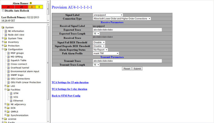
AU4/AU3 parameters
Parameter |
Description |
Default Value |
Acceptable Value |
|---|---|---|---|
Signal Label |
The payload signal label. |
|
The acceptable values include:
The signal Label field will be automatically assigned a value depending on the type of cross-connect provisioned. |
Connection Type |
Parameter to select the type of cross-connects that can be created. |
Allow both Lower Order and Higher Order Connections |
|
Receive Parameters |
|||
Received Signal Label |
The payload type or the Signal label received on the AU path. For example, tug_structure, asynchronous_container3, unequipped, etc. |
-- |
-- |
Expected Trace |
The path trace that is expected to be received on AU path. The Transmit Trace Length and Expected Trace Length must be the same. |
RX_Unallocated |
The received message can be 16 or 64 characters long. |
Expected Trace Length |
The length of the section path trace that is expected to be received. |
16 |
The length can be 16 or 64. |
Received Trace |
The AU path trace that is received. |
-- |
-- |
Signal Fail BER Threshold |
Parameter to indicate the threshold for signal fail Bit Error Rates (BER) beyond which alarm is raised. When Disable is selected, no threshold exists for the signal fail BERs and alarms are not raised. |
Disable |
|
Signal Degrade BER Threshold |
Parameter to indicate the threshold for signal degrade Bit Error Rates (BER) beyond which alarm is raised. When Disable is selected, no threshold exists for the signal degrade BERs and alarms are not raised. |
Disable |
|
Alarm reporting status |
Allows you to select the alarm reporting status of the interface.
|
Report |
|
Path alarm profile |
Parameter to assign the alarm profile for the Path. |
Mask TIM |
|
Transmit Parameters |
|||
Transmit Trace |
The message transmitted in the AU on J1 byte. |
Tx_Unallocated |
The trace message can be of 16 or 64 characters long. |
Transmit Trace Length |
The length of the section path trace to be sent. The Transmit Trace Length and Expected Trace Length must be the same. |
16 |
The length can be 16 or 64. |