![]()
![]()
![]()
![]()
|
|
|
|
|
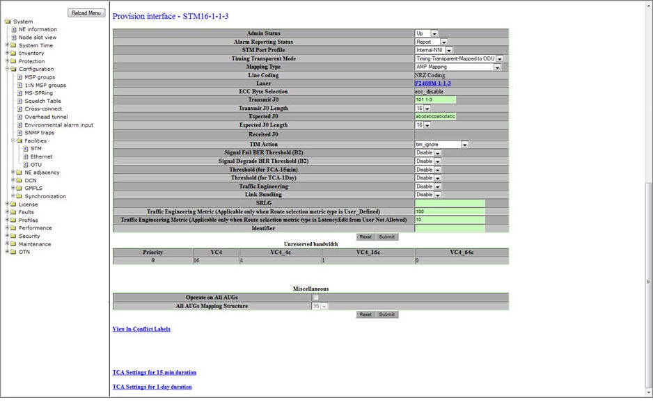
Perform the steps given below to provision interface parameters of a STM port.
A click on Back link will direct you to Provision interface preview pane of the same interface.
Provision interface- STM parameters
Parameter |
Description |
Default Value |
Acceptable Value |
|
|---|---|---|---|---|
Admin Status |
Allows you to select the administrative status of the interface.
|
Up |
|
|
Alarm Reporting Status |
Allows you to select the alarm reporting status of the interface.
|
Report |
|
|
STM Port Profile |
Allows you to select the STM port profile. |
Internal-NNI |
|
|
Timing Transparent Mode |
Allows you to enable or disable Timing Transparent Mode (TTM) on a client side port.
|
No Timing-Transparent-Mapping |
|
|
Mapping Type |
Allows you to select the mapping type from the drop down list. The value is 'Mapping Not Applicable' by default, if Timing Transparent Mode is set as 'No Timing-Transparent-Mapping'. NOTE: In case of TTM enabled STM-16/64 port, only 'AMP Mapping' is supported. |
Mapping Not Applicable |
|
|
Line Coding |
Displays the type of line coding being used (NRZ coding). This field is not configurable. |
-- |
-- |
|
Laser |
Displays the laser being used. Click on the link to view the Laser details. For more information, refer to Viewing Laser Details. The laser details are displayed when a SFP/XFP module is physically present on the port and also when the SFP/XFP image is present, except few parameters. |
-- |
-- |
|
ECC Byte Selection |
Displays the established Embedded Communication Channel on the interface as:
This field is not configurable. |
-- |
-- |
|
Transmit J0 |
Allows you to enter the Regenerator Section/Section trace message to be transmitted. Maximum length is as specified by the Transmit J0 Length and padded with spaces for strings less than specified length. |
abcdabcdabcdabc |
Any alphanumeric value |
|
Transmit J0 Length |
Allows you to select the transmit length of Regenerator Section/Section trace. |
16 |
|
|
Expected J0 |
Allows you to enter the expected received Regenerator Section/Section trace value. |
abcdabcdabcdabc |
Any alphanumeric value |
|
Expected J0 Length |
Allows you to select the length of the expected received Regenerator Section/Section trace message. |
16 |
|
|
Received J0 |
Displays the received Regenerator Section/Section trace message. |
-- |
-- |
|
TIM Action |
TIM Action settings control handling of mismatches between received and expected trace messages. Allows you to select the action taken on trace identifier match as:
|
tim-ignore |
|
|
Signal Fail BER Threshold (B2) |
Allows you to enable or disable Signal Fail BER thresholds.
|
Disable |
|
|
Signal Degrade BER Threshold (B2) |
Allows you to enable or disable Signal Degrade BER thresholds.
|
Disable |
|
|
Threshold (for TCA-15min) |
Parameter to enable TCA (Threshold Crossing Alerts) for 15 minutes duration.
|
Disable |
|
|
Threshold (for TCA-1Day) |
Parameter to enable TCA for 1 day duration.
|
Disable |
|
|
Traffic Engineering |
Allows you to enable or disable traffic engineering on the port. On enabling, the port becomes a part of GMPLS cloud. |
Disable |
|
|
Link Bundling |
Allows you to enable or disable link bundling on the port. In case of multiple paths between two nodes and link bundling enabled on all the links, protocols namely OSPF-TE, RSVP, and CSPF will be enabled and the related information will be shared via a single Bundled Interface created. In essence, only one adjacency shall be created with that neighbor using any non-faulty link. |
Disable |
|
|
SRLG |
Enter the SRLG identifier for the port to be used for SRLG type disjointness. Ensure that this identifier is same on the port of the neighboring node. |
-- |
Any numeric value |
|
Traffic Engineering Metric (Applicable only when Route selection metric type is User_Defined) |
Allows you to enter the cost value of the preferred link for routing when the Route Selection Metric is set as User_Defined while editing GMPLS. |
100 |
-- |
|
Traffic Engineering Metric (Applicable only when Route selection metric type is Latency.Edit from User Not Allowed) |
Displays the Delay Measurement value in terms micro seconds. The value gets refreshed when the user manually refreshes the DM value from Performance Monitoring page. |
-- |
-- |
|
Identifier |
Allows you to enter the name (identity) for the STM port. |
-- |
Alphanumeric characters |
|
Unreserved Bandwidth |
||||
Priority |
Displays the priority for VC. |
-- |
-- |
|
VC4 |
Displays the number of unreserved VC4 channels. |
-- |
-- |
|
VC4_4c |
Displays the number of unreserved VC4_4c channels. |
-- |
-- |
|
VC4_16c |
Displays the number of unreserved VC4_16c channels. |
-- |
-- |
|
VC4_64c |
Displays the number of unreserved VC4_64c channels. |
-- |
-- |
|
Miscellaneous |
||||
Operate on All AUGs |
Allows you to select/unselect the check box for bulk enabling/disabling of AUGs. NOTE: This parameter is not applicable if TTM is enabled on a given port. |
-- |
-- |
|
All AUGs Mapping Structure |
Allows you to enable (AU4) or disable AUG mapping for all the AUGs on the STM port. This parameter is editable when 'Operate on All AUGs' check box is selected. For TTM enabled ports, the value is set to '99' by default. |
Disable |
|
|