![]()
![]()
![]()
![]()
|
|
|
|
|
Tributary Units (TU) can be provisioned only after TU cross-connects are created. It is possible to retrieve or view the TU parameters only when TU is acting as a protecting member for a connection. The Transmit Trace and Expected Trace field are editable only for add/drop cross-connects. The Expected trace field is not editable for pass through cross-connects.
Perform the steps given below to provision TU.
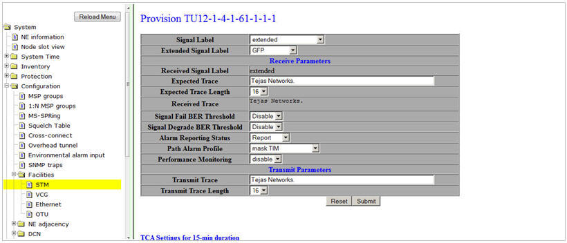
TU parameters
Parameter |
Description |
Default Value |
Acceptable Value |
|---|---|---|---|
Signal Label |
The payload signal label. The value assigned depends on the cross-connect provisioned. The Signal Label field is made user provisionable to avoid the Signal Label Mismatch in case of connectivity between nodes of multi vendor networks. |
Unequipped when there are no cross-connects provisioned |
Acceptable values:
|
Extended Signal Label |
The payload type or the Signal label received on the TU path. The value assigned depends on the cross-connect provisioned. The Extended Signal Label option is ignored for TU-3 and TU-12 pass through cross-connects. |
GFP for add drop Ethernet cross-connects |
Acceptable values:
|
Receive Parameters |
|||
Received Signal label |
The payload type or signal label received on the TU path. For example, tug structured, asynchronous_container3. |
-- |
-- |
Transmit Trace |
The path transmitted in the TU on J1 byte. |
Tejas Networks |
The trace can be 16 or 64 characters long. |
Transmit Trace Length |
The length of the section path trace to be sent. |
16 |
The length can be 16 or 64 |
Expected trace |
The path trace that is expected on the TU path. |
Tejas Networks |
The trace message can be 16 or 64 characters long. |
Expected Trace Length |
The length of the expected section path trace. |
16 |
The Length can be 16 or 64. |
Received Trace |
The TU path trace that is received. |
Tejas Networks |
-- |
Signal Fail BER Threshold |
Parameter to indicate the threshold for signal fail Bit Error Rates (BER) beyond which alarm is raised. |
1e-3 |
Acceptable values include 1e-3, 1e-4, 1e-5 and Disable. When Disable is selected, no threshold exists for the signal fail BERs and alarms are not raised. |
Signal Degrade BER Threshold |
Parameter to indicate the threshold for signal degrade Bit Error Rates (BER) beyond which alarm is raised. |
1e-6 |
Acceptable values include 1e-3 to 1e-9 and Disable. When Disable is selected, no threshold exists for the signal degrade BERs and alarms are not raised. |
Alarm Reporting Status |
Allows you to select the alarm reporting status of the interface.
|
Report |
|
Path Alarm Profile |
Parameter to assign the alarm profile for the Path. |
mask TIM |
|
Performance Monitoring |
Performance Monitoring can be enabled or disabled. |
Disable |
|
Transmit Parameters |
|||
Transmit Trace |
The TU path trace that is received. |
Tejas Networks |
-- |
Transmit Trace Length |
The length of the transmitted section path trace. |
16 |
The Length can be 16 or 64. |
NOTE 1: Presence of unprovisioned TU on the far end node leads to no VCAT overhead transmission. The alarm raised due to the above consequence is Loss of VCAT multiframe on TU.
NOTE 2: If the STM-N ports are provisioned in an MSP configuration, then you need to select the TU for the corresponding work port in order to edit the TU parameters. The settings will be automatically propagated to the protection TU.