There are various versions of Optical Fiber based Amplifiers (OFA) Erbium Doped Fiber Amplifiers (EDFAs) which can be used for multichannel amplification up to 80 Channels. This card is supported in TJ1600 Type-11SR, TJ1600 Type-6SR and TJ1600 Type-2SR chassis.
The following figure shows the front panel view of Single OFA (OFA-C-S20-VG) and Dual OFA (OFA-C-D20-LVG) cards with default filler:


Power specifications - OFA Cards
Specification |
Range |
|---|---|
Input Voltage |
-48V DC |
Power consumption (maximum) |
40W |
The visual indicators on the OFA card include two LEDs, the Active and the Status LEDs.
Possible LED status and their significance- OFA Cards
Card State |
Status LED |
Active LED |
Card initialization: State before the card initialize is complete on card insertion. |
Amber (Steady) |
Amber (Steady) |
Card in service: Initialization complete and card in service. |
Green (Steady) |
Green (Steady) |
Card mis-match: Node has already configured the slot with some other card. |
Amber |
Amber |
Card failed during boot up. |
Red |
Amber |
Card failed while in-service. |
Red |
Green |
Improper jack in of the card |
Green (Blinking) |
Green (Blinking) |
Hard Reset: All devices reset, FPGAs cleared and reprogrammed. Goes to initializing state next. |
Amber |
Amber |
Soft Reset: Software is restarted, devices are reinitialized with provisioning. Goes to initializing state next. |
Green |
Green |
Early Ejector LED status: One ejector is removed (contains one ejector switch in right). |
OFF |
Amber |
There are LEDs provided for Amplifier input (Rx) port and output (Tx) port. LED is either OFF or Glow RED.
Fixed Gain EDFA: Fixed gain EDFA design gives the flat gain for all DWDM channels at the designed gain known as Designed Flat Gain (DFG). When the gain is changed other than DFG, each channel is amplified differently giving a gain tilt. Following card types are available:
Fixed Gain OFA Card Types
Fixed Gain OFA Description |
Model number |
|---|---|
Fixed Gain amplifier, single module with 17dBm output power in C-band. |
OFA-C-S17-FG |
Fixed Gain amplifier, dual modules with 17dBm output power in C-Band. |
OFA-C-D17-FG |
Fixed High Gain amplifier, single module with 20dBm output power in C-band. |
OFA-C-S20-HG |
Fixed High Gain amplifier, dual modules with 20dBm output power in C-band. |
OFA-C-D20-HG |
Fixed Low Gain amplifier, single module with 20dBm output power in C-band. |
OFA-C-S20-LG |
Fixed Low Gain amplifier, dual modules with 20dBm output power in C-band. |
OFA-C-D20-LG |
Variable Gain EDFA: Variable Gain EDFA can give the flat gain for all channels over designed gain range. When the gain is changed other than DFG, each channel is amplified differently giving a gain tilt. This tilt can be compensated by adjusting the gain tilt setting. Following card types are available:
Variable Gain OFA Card Types
Variable Gain OFA Description |
Model number |
|---|---|
Variable Gain amplifier, single module with 20dBm output power in C-band. |
OFA-C-S20-VG |
Variable Gain amplifier, dual modules with 20dBm output power in C-band. |
OFA-C-D20-VG |
Low Variable Gain DWDM amplifier, single port with 20dBm output power in C-band. |
OFA-C-S20-LVG |
Low Variable Gain DWDM amplifier, dual ports with 20dBm output power in C-band. |
OFA-C-D20-LVG |
Mixed Variable Gain (Low and High Gain) DWDM amplifier, dual ports with 20dBm output power in C-band. |
OFA-C-D20-MVG |
Variable gain with Mid Stage Access EDFA: Following card types are available:
Variable gain with Mid Stage Access OFA Card Types
Variable gain with Mid Stage Access OFA Description |
Model number |
Variable gain with Mid Stage Access, single module with 20dBm output power in C Band. |
OFA-C-S20-MS-VG |
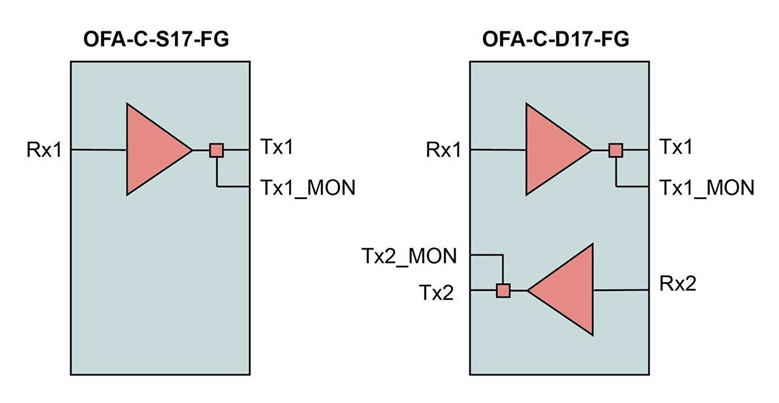
The different versions of OFA cards mentioned above are used for optical amplification in POTP and DWDM configuration of the product. The schematic diagram of the cards with single and dual module varieties is as follows:
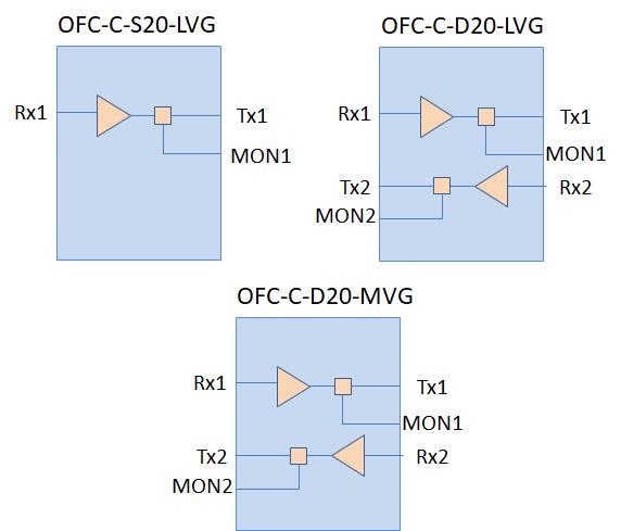
The schematic diagram of variable gain OFA is as follows:
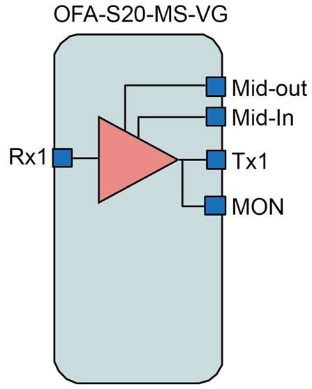
The schematic diagram of mid-stage OFA is as follows:
The following schematic diagram describes the connectivity of the OFA cards with OSC filter module which can be plugged into OFA card. The fiber connectivity between the OFA cards and the OSC filter module is external to the cards:
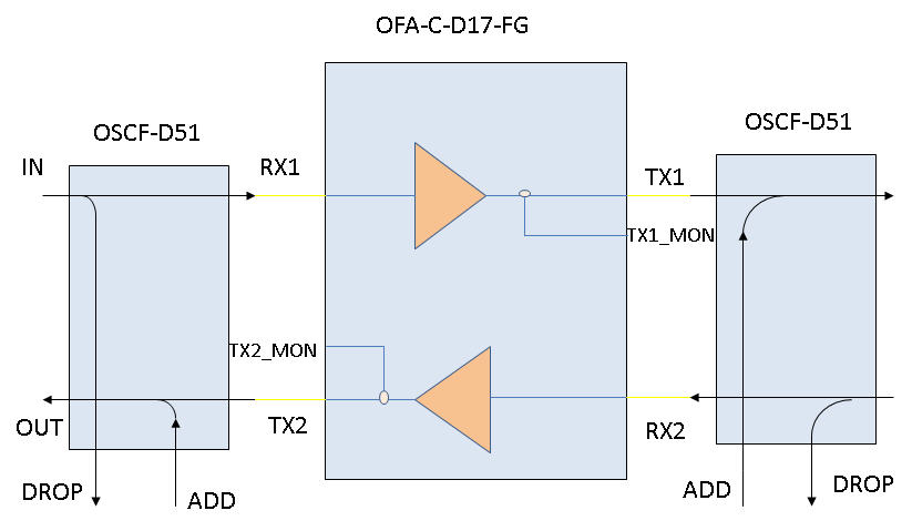
The fiber connectivity between the OFA cards and the OSC filter module is external to the cards:
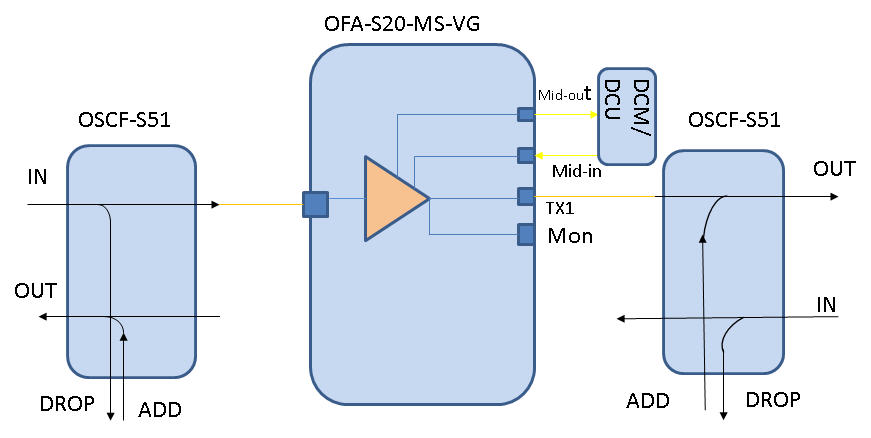
Typical specification of the fixed gain and the variable gain OFAs are as follows:
The following table summarizes the different parameters of fixed gain OFA card and its typical values:
Fixed Gain OFA Card parameters and typical values
Specification |
Units |
OFA-C-S17-FG & OFA-C-D17-FG |
OFA-C-S20-HG & OFA-C-D20-HG |
OFA-C-S20-LG & OFA-C-D20-LG |
|---|---|---|---|---|
Total operating wavelength range |
nm |
1529 nm to 1565 nm |
1529 nm to 1565 nm |
1529 nm to 1565 nm |
THz |
191.6 to 195.9 |
191.6 to 195.9 |
191.6 to 195.9 |
|
Input power range |
dBm |
-5 to -35 |
-5 to -35 |
-5 to -35 |
Design Flat Gain (DFG) |
dB |
23 |
26 |
22 |
Noise Figure, at DFG and minimum input |
dB |
5.5 |
5.5 |
5.5 |
Output power range |
dBm |
-5 to 17 |
-5 to 20 |
-5 to 20 |
Output Power Monitor port (-20dB) |
|
Available |
Available |
Available |
Polarization dependent gain |
dB |
0.5 |
0.5 |
0.5 |
Polarization mode dispersion |
ps |
0.7 |
0.7 |
0.7 |
Optical return loss |
dB |
>40 |
>40 |
>40 |
Operating modes |
- |
AGC, APC, ACC |
AGC, APC, ACC |
AGC, APC, ACC |
Power consumption |
W |
14 W for OFA-C-S17-FG |
16 W for OFA-C-S20-HG |
16 W for OFA-C-S20-LG |
24 W for OFA-C-D17-FG |
27 W for OFA-C-D20-HG |
27 W for OFA-C-D20-LG |
||
Mechanical dimension |
- |
One Full slot width |
One Full slot width |
One Full slot width |
The table below summarizes the different parameters of variable gain OFA card and its typical values:
Variable Gain OFA parameters and typical values
Specification |
Units |
OFA-C-S20-VG & OFA-C-D20-VG |
OFA-C-S20-MS-VG |
|---|---|---|---|
Total operating wavelength range |
nm |
1529 nm to 1565 nm |
1529 nm to 1565 nm |
THz |
191.6 to 195.9 |
191.6 to 195.9 |
|
Input power range |
dBm |
-35 to 5 |
-35 to 5 |
Nominal Gain |
dB |
15 to 30 |
16 to 28 |
Output power range |
dBm |
-5 to 20 |
-7 to 20 |
Mid-stage Loss |
dB |
NA |
8.5 |
Noise figure |
dB |
G≥16dB: 10.7 |
G≥16dB: 13 |
G≥18dB: 8.0 |
G≥19dB: 8.8 |
||
G≥21dB: 6.5 |
G≥22dB: 7.3 |
||
G≥24dB: 5.7 |
G≥25dB: 6.6 |
||
G≥27dB: 5.6 |
G≥28dB: 5.9 |
||
G≥30dB: 5.5 |
- |
||
Output power Monitor port(-20db) |
- |
Available |
Available |
polarization dependent gain |
dB |
0.5 |
0.5 |
Polarization mode dispersion |
ps |
0.7 |
0.7 |
Optical return loss |
dB |
>40 |
>40 |
Operating modes |
- |
AGC, APC, ACC |
AGC, APC, ACC |
Power consumption |
W |
16 W for OFA-C-S20-VG, 28 W for OFA-C-D20-VG |
25 W for OFA-C-S20-MS-VG |
Mechanical dimension |
- |
One Full slot width |
One Full slot width |
Extended gain range |
dB |
30.1 to 33 |
28.1 to 33 |
NOTE: Above mentioned Variable Gain Amplifiers supports extended gain operation of up to 33dB.
The table below summarizes the different parameters of Lower variable gain OFA card and its typical values:
Lower Variable Gain OFA parameters and typical values
Specification
|
Units
|
OFA-C-S20-LVG & OFA-C-D20-LVG
|
OFA-C-D20-MVG Variable Gain Mode |
|
|---|---|---|---|---|
|
||||
Total operating wavelength range |
nm |
1530.0 to 1564.68 |
1529.0 to 1565.0 |
|
THz |
191.6 to 195.9 |
191.6 to 195.9 |
||
Input power range |
dBm |
-22 to 10 |
-35 to 5 |
|
Nominal Gain |
dB |
10 to 20 |
15 to 30 |
|
Extended Gain |
dB |
-- |
30.1 to 33 |
|
Output power range |
dBm |
-13 to 20 |
-5 to 20 |
|
Mid-stage Loss |
dB |
NA |
NA |
|
Noise figure |
dB |
G≥10dB: 10.5 |
G≥16dB: 10.7 |
|
G≥13dB: 8.0 |
G≥18dB: 8.0 |
|||
G≥15dB: 6.5 |
G≥21dB: 6.5 |
|||
G≥18dB: 5.5 |
G≥24dB: 5.7 |
|||
|
G≥27dB: 5.6 |
|||
|
G≥30dB: 5.5 |
|||
Output power Monitor port(-20db) |
- |
Available |
Available |
|
polarization dependent gain |
dB |
0.3 |
0.5 |
|
Polarization mode dispersion |
ps |
0.3 |
0.7 |
|
Optical return loss |
dB |
>40 |
>40 |
|
Operating modes |
- |
AGC, APC, ACC |
AGC, APC, ACC |
|
Power consumption |
W |
16 W for OFA-C-S20-LVG, 28 W for OFA-C-D20-LVG |
28 W for OFA-C-D20-MVG in VG mode. |
|
Mechanical dimension |
- |
One Full slot width |
One Full slot width |
NOTE: OFA-C-D20-MVG port values correspond to the values of OFA-C-D20-LVG in LVG mode.
OFA-C-D20-MVG in Variable Gain mode supports an extended gain operation of up to 33dB.