The Reconfigurable Optical Add Drop (ROADM) card can dynamically add drop any wavelength up to 80 Channels from the same physical ports and hence provide operational benefit compared to the fixed OADMs. This card is supported in TJ1600 Type-11SR and TJ1600 Type-6SR chassis.
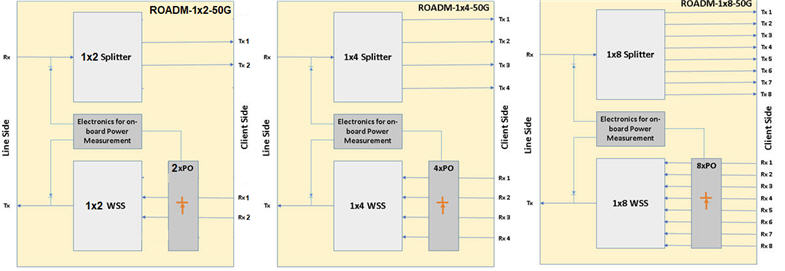
In addition to this, dynamic protection and restoration can be carried out in the optical layer. In ROADM card, the drop side is achieved by an optical splitter to broadcast all the signals and in the add side, a wavelength selective switch (WSS) is used to select the traffic from all the degrees or sides.
The 1x2 ROADM card can cater to 2 degree node and the 1x4 ROADM cards and 1x8 ROADM card can support up to 4 and 8 degrees, respectively.
The following figure shows the front panel diagram of ROADM cards:


Power Specifications – ROADM Cards
Specification |
Range |
|---|---|
Input Voltage |
-48V DC |
Power consumption (max) |
30W |
The visual indicators on the ROADM card include two LEDs, the ACTIVE and the STATUS LEDs.
Possible LED status and their significance – ROADM Cards
Card State |
Status LED |
Active LED |
Card initialization: State before the card initialize is complete on card insertion. |
Amber (Steady) |
Amber (Steady) |
Card in service: Initialization complete and card in service. |
Green (Steady) |
Green (Steady) |
Card mis-match: Network Element has already configured the slot with some other card. |
Amber |
Amber |
Card failed during boot up. |
Red |
Amber |
Card failed while in-service. |
Red |
Green |
Improper jack in of the card. |
Green(Blinking) |
Green(Blinking) |
Hard Reset: All devices reset, FPGAs cleared and reprogrammed. Goes to initializing state next. |
Amber |
Amber |
Soft Reset: Software is restarted, devices are reinitialized with provisioning. Goes to initializing state next. |
Green |
Green |
Early Ejector LED status: One ejector is removed (contains one ejector switch in right). |
OFF |
Amber |
There are mainly three types of Reconfigurable Optical Add Drop Multiplexer (ROADM) card available. They are 1x2 ROADM (ROADM-2-C-50G), 1x4 ROADM (ROADM-4-C-50G) and 1x8 ROADM (ROADM-8-C-50G), all with 50GHz support and hence can handle 80 Channels at 50GHz.
The schematic diagram of the ROADM cards is as follows:
In the drop directions optical splitters are used for broadcast and in the add direction WSS are used for select. All the cards have input port optical power monitoring. In addition, the egress port of the WSS is also monitored in order to detect and isolate physical faults.

Typical specification and functionalities of the ROADM cards are as follows:
Below tables summarizes different parameter and typical values:
Typical Specifications – ROADM Cards
Specification |
Units |
Values |
||
|---|---|---|---|---|
ROADM-1x8-50G |
ROADM-1x4-50G |
ROADM-1x2-C-50G |
||
Channel Plan(C- band, 50Ghz spacing) |
- |
80 |
80 |
80 |
Insertion Loss for Add Ports |
dB |
6.5 |
6.5 |
6.5 |
Insertion Loss for Drop Ports |
dB |
11 |
8 |
4 |
No of Add/Drop Ports |
- |
8 |
4 |
2 |
VOA range |
dB |
0-15 |
0-15 |
0-15 |
VOA step size |
dB |
0.1 |
0.1 |
0.1 |
Switching time |
ms |
300 |
300 |
300 |
Power Consumption |
W |
15 |
15 |
10 |
Connector type |
- |
LC/PC |
LC/PC |
LC/PC |
Slot width in the chassis |
- |
Two full slots |
One full slot |
One full slot |
The 100GHz channel version of the 4/8 degree ROADMs is available as ROADM-4-C-100G and ROADM-8-C-100G, respectively. Rest of the physical parameters remains same as the 50GHz Channel versions as given in table above.
NOTE: Above cards with existing hardware also supports C-band Flex grid (as per G.694.1) with channels granularity of 12.5GHz. Feature can be enabled with additional software license.