GMPLS (Generalized Multiprotocol Label Switching) is an extension of the MPLS signaling protocols to enable easy setup/restoration for use in Optical Transport Network (OTN) and Synchronous Digital Hierarchy (SDH).
NOTE: GMPLS is supported for OTN only for this release.
There are four Service Types or classes in GMPLS namely:
Perform the following steps to create OTN GMPLS circuit:


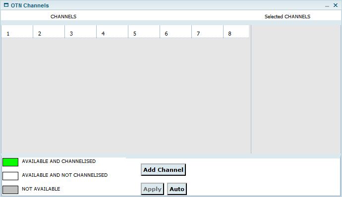
> Manually: Under CHANNELS, click the desired channel number(s) and click Add Channel. The channels(s) will be displayed under Selected CHANNELS. Click Apply.
> Automatically: Click Auto button. Depending on the Capacity, the required number of channels will automatically get listed under Selected CHANNELS. Click Apply.
Attributes of Create Circuit - OTN GMPLS
Attribute |
Description |
|---|---|
Create Circuit |
|
Circuit Type |
Select the type of circuit as 'P2P'. |
Sub Type |
Select the sub type of circuit as 'OTN Circuit'. |
Restoration Scheme |
Select the check box to enable GMPLS. |
Circuit name |
Enter the name of circuit. |
Customer |
Enter the name of the customer. The drop-down list will be displayed after entering the character in the field. If the drop-down list does not display any customer names, the user can create customer by clicking on the C link available against this field. The Create Customer page is displayed. Refer to the Manage Customers section for further details. |
Capacity |
Select the capacity from the drop down menu:
NOTE: 'ODUflex' option is not supported for GMPLS circuit. |
Direction |
The direction is always Bi (Bi-directional). |
Time slot selection |
By default 'Manual' option will be selected. This parameter is not configurable. |
Higher Order |
Check this box if higher order circuit has to be created. This parameter is not configurable. NOTE: Single Node Higher Order circuit can be discovered in the NMS by enabling the singleton support. |
Enabe CST |
This parameter is not configurable. |
Class Of Service |
Select the class of Service from the drop down menu.
|
Disjointness |
Disjointness is to ensure no element is common to mitigate the risks. It is supported in 1_1_R and 1_1_F class of services. Select the option from following:
|
Disjointness Degree |
Disjointness degree is parameter to allow load sharing on the links.
|
Priority |
Assign the priority to the circuit if multiple services are traversing on the link. Highest priority is 0 and lowest is 7. On fiber cut, highest priority services are rerouted first. |
Auto Planned |
Select the check box to select the path automatically, after entering the source and destination information. |
TL Bandwidth Calculation |
Select the check box to view the bandwidth on the Topological links, displayed after Route creation. |
Source Information |
|
SrcTrafficType |
By default 'OTN' option will be selected. This parameter is not configurable. |
Node |
Enter the source node name. On entering a letter, the list pertaining to that letter will be displayed. NOTE: On selecting the option IP, you can enter the IP instead of the node name. |
Port |
Select the desired port from drop down menu. |
Time slot |
Click M (Select TimeSlots) to select the time slot on the desired port. |
NOTE: The Add source client port protection option enables you to protect the source port. |
|
Destination Information |
|
DestTrafficType |
By default 'OTN' option will be selected. This parameter is not configurable. |
Node |
Enter the destination node name. On entering a letter, the list pertaining to that letter will be displayed. NOTE: On selecting the option IP, you can enter the IP instead of the node name. |
Port |
Select the desired port drop down menu. |
Time slot |
Click M (Select TimeSlots) to select the time slot on the desired port. |
NOTE: The Add destination client port Protection option enables you to protect the destination port. |
|