Points to Remember
While creating an OTN Circuit, consider the following points:
Perform the following steps for creation of an OTN circuit:
> Click the Node check box and enter the IP address of the source node in the IP text box; or
> Enter name of the source node in the IP text box.

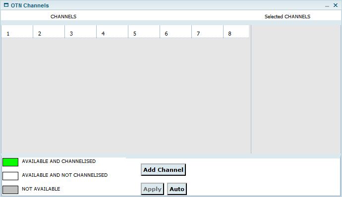
> Manually: Under CHANNELS, click the desired channel number(s) and click Add Channel. The channels(s) will be displayed under Selected CHANNELS. Click Apply.
> Automatically: Click Auto button. Depending on the Capacity selected in Step 2b, the required number of channels will automatically get listed under Selected CHANNELS. Click Apply.
The selected channel(s) will now be displayed in TimeSlot field on Create Circuit window.


A Create Circuit: Success window is displayed. Click Manage Circuit link to view the details of the circuit created or click Close to exit the window.
Attributes of Create Circuit- OTN
Attribute |
Description |
|---|---|
Common Circuit Info |
|
Circuit Type |
Allows you to select the type of circuit by clicking on the radio button:
|
Sub Type |
Select the sub circuit type as 'OTN Circuit' from the drop down menu. |
Circuit name |
Allows you to enter a name for the circuit. Acceptable values include characters A to Z, a to z, 0 to 9, _(underscore), -(hyphen), .(dot), &(ampersand), space. |
Customer |
Enter the name of the customer. The drop-down list will be displayed after entering the character in the field. If the drop-down list does not display any customer names, the user can create customer by clicking on the C link available against this field. The Create Customer page is displayed. For more information, refer to the Manage Customers section. |
Capacity |
Allows you to select the capacity for circuit creation. Values displayed in the drop down options depend on the Circuit Type selected by the user.
|
Direction |
The direction is always Bi (Bi-directional). |
Copies |
Allows you to enter the number of circuit copies desired to create. This parameter is displayed for OTN and P2P circuit type. |
Higher Order |
Select the check box if higher order circuit has to be created. NOTE: Single Node Higher Order circuit can be discovered in the TJ5500 by enabling the singleton support. |
Enable CST |
Select the check box to enable Client Signal Termination. This option is supported only for OTN circuits. NOTE: Circuit creation involving CST is only supported for ODU1 and ODU2 capacities. |
Time slot selection |
By default the time slot selection is in 'Manual' for OTN circuits. |
Class Of Service |
Select the type of protection required from the drop down menu.
|
TL BandWidth Calculation |
Select the check box to view the bandwidth on the Topological links, displayed after Route creation. |
Source/Destination Information |
|
SrcTrafficType DestTrafficType |
Allows the user to select the source and destination traffic pattern from the options:
|
Node/IP |
Select the Node check box and enter the IP Address of the Source/Destination node in IP text box provided; or enter the node name in IP text box. On entering a letter, the list pertaining to that letter will be displayed. |
Port |
On entering a valid IP, available ports will be displayed in the drop down options depending on the capacity selected. Select the desired port. |
TimeSlot |
Click the M link and select the desired time slots. |
Add/Remove source protection |
Click the link to add or remove protection to the Source port. This option is not applicable to VCG circuit types. For adding protection, enter the Port and TimeSlot details. |
Add/Remove destination protection |
Click the link to add or remove protection to the Destination port. This option is not applicable to VCG circuit types. For adding protection, enter the Port and TimeSlot details. |
Start Route Creation |
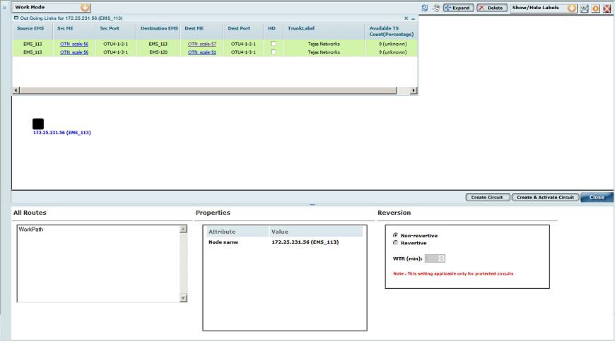
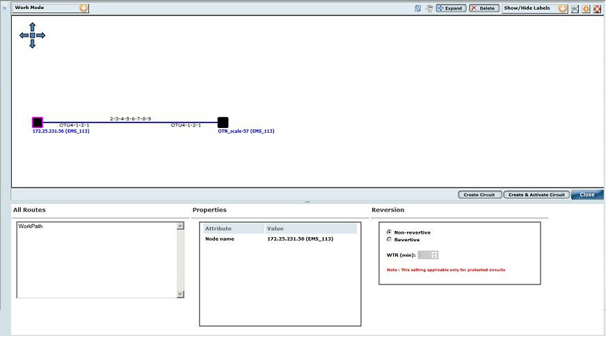
Click this button to initiate route creation after entering valid circuit creation details. |