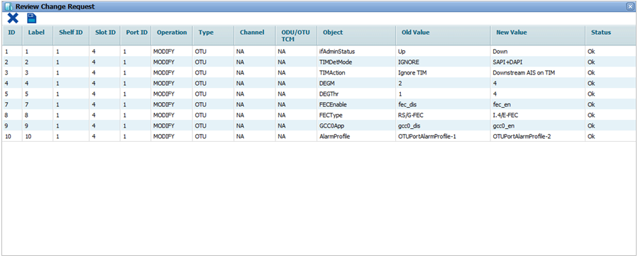
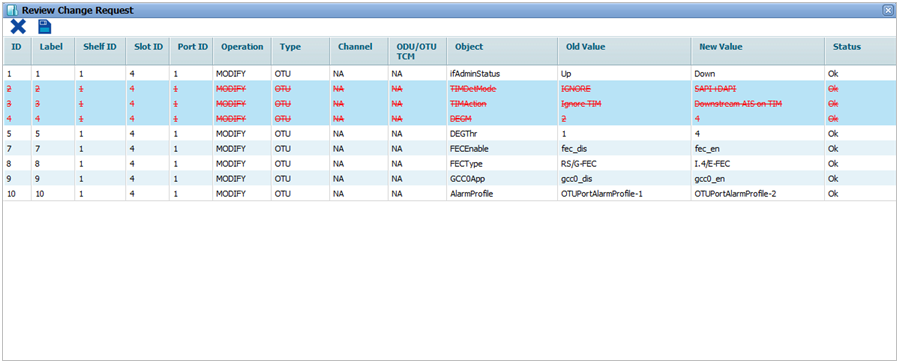
Perform the following steps to provision the physical port parameters of an OTU port on OTN supporting cards:


![]() (show changes saved) button allows you to view the saved changes in Recently saved changes window. This button is available only when the timer is visible.
(show changes saved) button allows you to view the saved changes in Recently saved changes window. This button is available only when the timer is visible.
OTU Physical Port details
Parameter |
Description |
Default Value |
Acceptable Value |
|---|---|---|---|
ID |
Displays the OTU port number in ci-si-pn format. |
-- |
-- |
Label |
Displays the OTU port number in ci-si-pn format. |
-- |
-- |
Admin Status |
Allows you to select the status of the interface as:
|
Up |
Up Down |
TIM Detection Mode |
Allows you to select the TIM (Trace Identifier Mismatch) detection mode. The detection of TIM is based on a comparison between the expected Trial Trace Identifier (TTI) and the received TTI.
|
IGNORE |
|
TIM Action |
Allows you to select the action to be taken upon detection from the following options:
|
Ignore TIM |
|
Degraded Signal Defect |
Allows you to select the value (in seconds), exceeding which signal fail alarm is raised for errors. |
02 |
02 to 10 |
Deg Threshold |
Allows you to select the threshold (in percentage), exceeding which signal fail alarm is raised for errors. |
01 |
01 to 100 |
DAPI Transmitted |
Allows you to enter the destination access point identifier to be transmitted. |
abcdabcdabcd |
Up to 16 alphanumeric characters including special characters. |
SAPI Expected |
Allows you to enter the expected source access point identifier. |
abcdabcdabcd |
Up to 16 alphanumeric characters including special characters. |
DAPI Expected |
Allows you to enter the expected destination access point identifier. This parameter is editable when TIM Detection Mode is set as 'DAPI TIM' or 'SAPI+DAPI TIM'. |
abcdabcdabcd |
Up to 16 alphanumeric characters including special characters. |
SAPI Transmitted |
Allows you to enter the source access point identifier to be transmitted. |
abcdabcdabcd |
Up to 16 alphanumeric characters including special characters. |
Forward Error Correction |
Allows you to enable or disable FEC on the port. |
Disable |
|
FEC Type |
Allows you to select the FEC type as either RS/G-FEC or 1.4/E-FEC. |
RS/G-FEC |
|
GCC0 Application |
Allows you to enable or disable the GCC0 byte for management channel communication. |
Disable |
|
OTU Port Alarm Profile |
Allows you to select the default OTU port profile. |
Internal |
|
Threshold (for TCA-15min) |
Allows you to enable or disable the TCA for 15 minutes interval.
|
Disable |
|
Threshold (for TCA-1Day) |
Allows you to enable or disable the TCA for 1 day duration.
|
Disable |
|
Traffic Engineering |
Allows you to enable or disable traffic engineering on the port. On enabling, the port becomes a part of GMPLS cloud and Remote Port Label set will get displayed with details of un-channelized timeslots, free and busy channels on remote end. |
Disable |
|
SRLG |
Allows you assign a SRLG identifier. The same value should be assigned on the remote port of the remote/far end node to which it is connected in a GMPLS network. |
-- |
Any numeric value |
Link Bundling |
Allows you to enable or disable link bundling on the port. In case of multiple paths between two nodes and link bundling enabled on all the links, protocols namely OSPF-TE, RSVP, and CSPF will be enabled and the related information will be shared via a single Bundled Interface created. In essence, only one adjacency shall be created with that neighbor using any non-faulty link. When enabled, auto-discovery on that port will get enabled followed by creation of an IBC (BUNDLED_LINK) automatically. NOTE: Any existing IBC will have to be deleted in order to enable link bundling on that port. |
Disable |
|
TE Metric |
Allows you to enter the value for the port when the route selection metric under GMPLS is set as User_Defined. The same value should be entered on the far end connected port. |
100 |
-- |
Latency TE Metric |
Displays the Delay Measurement value in terms micro seconds. The value gets refreshed when the user manually refreshes the DM value from Performance Monitoring page. |
-- |
-- |