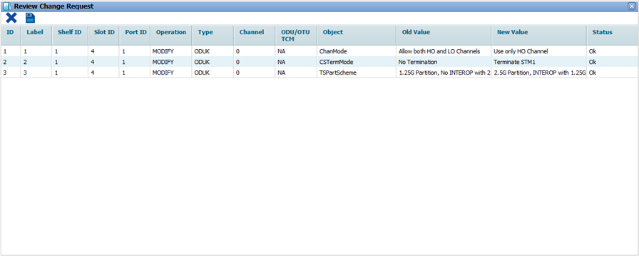
The OTU port on OTN supporting card will have an ODUk logical interface associated with it. User can view and configure the properties of that ODUk interface under ODUK Details tab on Manage Ports page.
Perform the following steps to provision the parameters of an ODUk interface associated with an OTU port:

![]() (show changes saved) button allows you to view the saved changes in Recently saved changes window. This button is available only when the timer is visible.
(show changes saved) button allows you to view the saved changes in Recently saved changes window. This button is available only when the timer is visible.
ODUk Details
Parameter |
Description |
Default Value |
Acceptable Value |
|---|---|---|---|
Functional Mode |
Displays the functional mode of the ODU interface as 'Source and Sink'. This field is not editable. |
Source and Sink |
-- |
Channelization Mode |
Allows you to select the channelization mode. |
Allow both HO and LO Channels |
|
Client Signal Termination Mode |
Select the required termination mode from the drop down list. Options namely No Termination, Terminate STM16, Terminate STM64 are supported in this product release. NOTE: When CST is enabled on an interface, a logical port is created of the equivalent capacity. |
No termination |
|
Tributary Slot Partition Scheme |
Allows you to select the partition scheme for tributary slot. On selecting '1.25G Partition, No INTEROP with 2.5G' option, the user is allowed to create ODU0 and ODU1 channels whereas on selecting '2.5G Partition, INTEROP with 1.25G', creating ODU0 channel is not supported. |
1.25G Partition, No INTEROP with 2.5G |
|
Connection Indexing Policy |
Displays the Connection Indexing Policy as ‘TPN And TS based policy’. |
TPN And TS based policy |
-- |
MSIM Policy |
Allows you to check for MSIM (Multiplex Structure Identifier Mismatch). |
No Check |
|
GCC1 Application |
Allows you to enable or disable GCC1 application. |
Disable |
|
GCC2 Application |
Allows you to enable or disable GCC2 application. |
Disable |
|
Maintenance And Test Signal |
Allows you to select desired option for network maintenance. |
None |
|
TIM Detection Mode |
Allows you to select the TIM (Trace Identifier Mismatch) detection mode. The detection of TIM is based on a comparison between the expected Trial Trace Identifier (TTI) and the received TTI.
|
IGNORE TIM |
|
Degraded Signal Defect |
Allows you to select the degraded signal defect value in seconds which defines the time after which the degrade alarm is raised. |
02 |
02 to 10 |
DEG threshold |
Allows you to select the threshold percentage value for the signal from the drop down list. |
01 |
01 to 100 |
Threshold (for TCA-15min) |
Allows you to enable or disable the TCA for 15 minutes interval.
|
Disable |
|
Threshold (for TCA-1Day) |
Allows you to enable or disable the TCA for 1 day duration.
|
Disable |
|
Received DAPI |
Displays the received destination access point identifier. |
-- |
-- |
DAPI Expected |
Allows you to enter the expected destination access point identifier. This parameter is editable when TIM Detection Mode is set as 'DAPI TIM' or 'SAPI+DAPI TIM'. |
abcdabcdabcd |
Up to 16 alphanumeric characters including special characters. |
Received SAPI |
Displays the received source access point identifier. |
-- |
-- |
SAPI Expected |
Allows you to enter the expected source access point identifier. This parameter is editable when TIM Detection Mode is set as 'SAPI TIM' or 'SAPI+DAPI TIM'. |
abcdabcdabcd |
Up to 16 alphanumeric characters including special characters. |
Payload Type Received |
Displays the payload type received on the client port. |
Open Connection |
-- |
PayLoad Type Expected |
Allows you to select the payload type to be carried on OTN frame that is expected on the client port. |
Asynchronous CBR Mapping |
|
SAPI Transmitted |
Allows you to enter the source access point identifier to be transmitted. |
abcdabcdabcd |
Up to 16 alphanumeric characters including special characters. |
DAPI Transmitted |
Allows you to enter the destination access point identifier to be transmitted. |
abcdabcdabcd |
Up to 16 alphanumeric characters including special characters. |
Payload Type Received |
Displays the payload type received on the client port. |
No Signal |
-- |
PayLoad Type Transmitted |
Allows you to select the payload type on OTN frame to be transmitted. |
Asynchronous CBR Mapping |
|
Alarm Profile |
Select the required alarm profile from the drop down list. |
mask TIM and PLM |
|