Previous Topic

Next Topic

Book Contents

Provision Ethernet interface parameters

Perform the following steps to provision the physical port parameters of an Ethernet port:
  1. Go to Configuration > Layer 1 menu and click Manage L1 Ports option. Manage Ports page is displayed.
  2. Do one of the following:
  3. Click Search Icon (Search Nodes). Shelf(s) and cards details of the node are listed under Node Tree pane.
  4. Click Ports drop-down for desired card and select the Ethernet port under Node Tree pane. The physical port parameters of the all the Ethernet ports under that card is displayed under ETH Port Details pane.
  5. Double-click the field desired to change. All parameters (except ID and Label) are editable. For more information, refer to ETH Port details table.
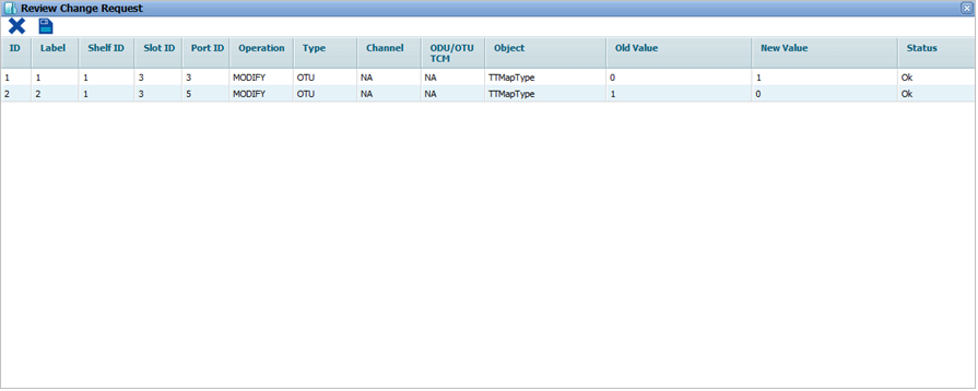
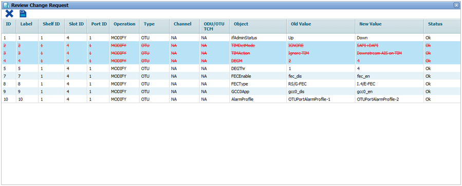
  6. Click Save icon (Save Changes). Review Change Request window is displayed. Object field displays the port parameters edited by the user with changed values under New Value field and previous values under Old Value field.

    Review Change Request- Port parameters

  7. Do one of the following:
  8. Click Save icon (Save Changes). Change Requests Status window is displayed listing the status of operation under Status field.
  9. Click (Close) to exit Change Requests Status window. A message Please refresh the Page or search Node. Automatically Refreshing the page in 3 minutes is displayed.
  10. For the changes to apply and get updated in TJ5500, refreshing operation is required to be performed. This can be done in any of the two ways mentioned as follows:

Ethernet port details

Parameter

Description

Default Value

Acceptable Value

ID

Displays the Ethernet port number in ci-si-pn format.

--

--

Label

Displays the Ethernet port number in ci-si-pn format.

--

--

Admin Status

Allows you to select the status of the interface as:

  • Up: Sets the interfaces in service.
  • Down: Sets the interfaces out of service.

Up

Up

Down

Alarm Reporting Status

Select the alarm reporting status of the interface.

  • Report: Reports alarms raised on Ethernet interface on Active alarms pane.
  • No-Report: Reports alarms raised on Ethernet interface on Suppressed alarms pane.

No-Report

  • No-Report
  • Report

Timing Transparent Mode

Enable or disable Timing Transparent Mode (TTM) on a client side port.

  • No Timing-Transparent-Mapping: Indicates that TTM is disabled on the Ethernet interface.
  • Timing-Transparent-Mapped to ODU: Indicates that TTM is enabled on the Ethernet interface. The client signals can now be mapped into OTU transport frames.

No Timing- Transparent- Mapping

  • No Timing- Transparent- Mapping
  • Timing-Transparent-Mapped to ODU

Mapping Type

This field gets updated depending upon the value selected in Timing Transparent Mode field. In case of no Timing-Transparent- Mapping, Mapping Type field will be selected as Mapping Not Applicable.

The mapping type supported are:

  • For 1G ETH port: GFP-T Mapping to ODU0
  • For 10G ETH port: BMP Mapping to ODU2e

Mapping Not Applicable

  • Mapping Not Applicable
  • AMP Mapping
  • BMP Mapping
  • GFP-F Mapping to ODUFlex
  • GFP-T Mapping to ODU0
  • BMP Mapping to ODU1e
  • GFP-F Mapping to ODU2
  • Extended GFP-F Mapping to ODU2
  • BMP Mapping to ODU2e
  • GMP Mapping
  • BMP Mapping to ODU1fc
  • BMP Mapping to ODU2fc
  • BMP Mapping to ODU4

Link Integrity

When link integrity is enabled, the receive data path is monitored for checking the link status.

Disable

  • Disable
  • Enable

See also

Manage L1 Ports

View L1 Port details

Edit card and line configuration

Provision OTU interface parameters

Provision ODUk interface parameters

Provision STM/OC interface parameters

Provision Fiber Channel (FC) interface parameters

Add ODUk channel

Add OTU and ODUk TCM level

Set port transceiver details

Configure DWDM port parameters