The OAM for Tunnels can be accessed from All Tunnels tab.
Perform the following steps to access the OAM details of complete tunnel information:
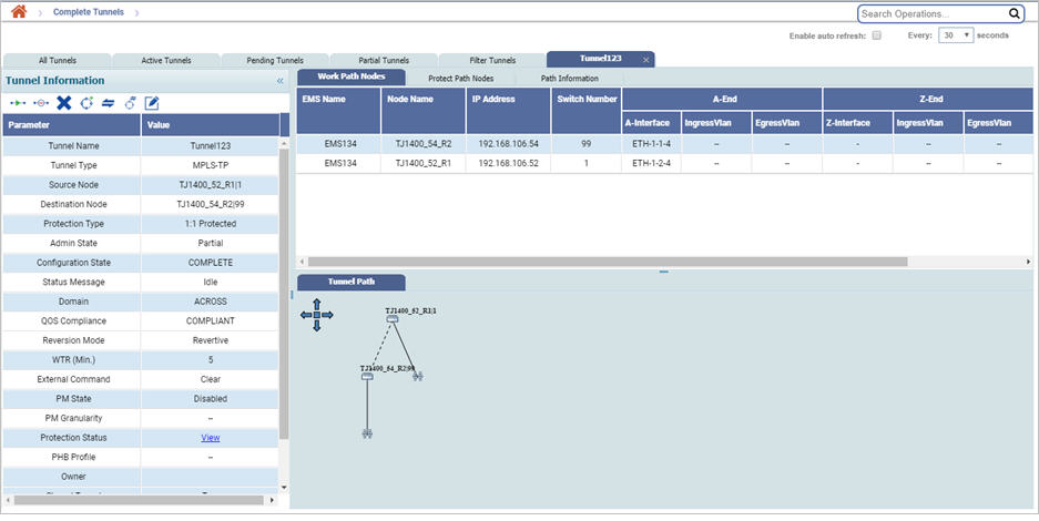
Tunnel information parameters
Parameter |
Description |
|---|---|
Tunnel Name |
Displays the tunnel name. |
Tunnel Type |
Displays the tunnel type as MPLS-TP. |
Source Node |
Displays the name of the source node. |
Destination Node |
Displays the name of the destination node. |
Protection Type |
Displays whether the tunnel unprotected or 1:1 protected. |
Admin State |
Displays the admin state of the tunnel. |
Configuration State |
Displays the configuration state of the tunnel. |
Status Message |
Displays the status message of the tunnel created. |
Domain |
Displays the tunnel domain. |
QOS Compliance |
Displays whether the tunnel is Qos Compliant or Non-Complaint. |
Reversion Mode |
Displays whether the reversion mode for the channel is revertive or non-revertive. |
WTR (Min.) |
Displays the time the node takes to switch traffic from protect channel to work channel after the fault on working channel clears. |
External Command |
Displays the external command executed on the tunnel. |
PM State |
Displays the performance management state as enabled or disabled. |
PM Granularity |
Displays the PM granularity of a PM enabled tunnel. |
Protection Status |
Click the View link to view the tunnel protection status of a protected tunnel in active state. This parameter is not applicable to an unprotected tunnel. |
PHB Profile |
Displays the per hop behavior profile associated. |
Owner |
Displays the owner name. |
Shared Tunnel |
Displays the share status of the tunnel as true or false. True indicates that the tunnel is shared while false indicates that the tunnel is exclusive. |
Creation Time |
Displays the creation time of the tunnel from NMS. In case of a NMS discovered tunnel, it will reflect the time at which the tunnel was discovered. |
Disjointedness |
Displays if the tunnel is SRLG Disjoint or not. |
Tunnel- Other parameters
Parameter |
Description |
|---|---|
Work Path Nodes/Protect Path Nodes |
|
EMS Name |
Displays the name of the EMS. |
Node Name |
Displays the name of the node. |
IP Address |
Displays the IP address of the node. |
Switch Number |
Displays the switch number. The switch number is identification number for switches and is used as the label of node boxes in the tunnel view. |
A-End Interface |
Displays the interface of remote node connected to the intermediate node towards east side. |
A-End - Ingress Vlan |
Displays the ingress VLAN value set for tagged MPLS tunnel at east side. |
A-End - Egress Vlan |
Displays the egress VLAN value set for tagged MPLS tunnel at east side. |
Z-End Interface |
Displays the interface of remote node connected to the intermediate node towards west side. |
Z-End - Ingress Vlan |
Displays the ingress VLAN value set for tagged MPLS tunnel at west side. |
Z-End - Egress Vlan |
Displays the egress VLAN value set for tagged MPLS tunnel at west side. |
Admin State |
Displays the admin state. |
Status |
Displays the status message of the tunnel created. |
MEPID |
Displays the ID for Maintenance End Points. |
MEP Status |
Displays the status message of the Maintenance End Points. |
Path Information |
|
Path |
Displays whether the path is work path or protect path. |
BVID |
Displays the Bridge VLAN ID of the Tunnel. BVID range is 2 - 4094. The value of CVID and SVID range supported is 1-4094. |
Admin State |
Displays the admin state of the path. |
Status |
Displays the status of the tunnel path. |
MD Name |
Displays the Maintenance Domain Level name. |
MD Level |
Displays the Maintenance Domain Level. This value range from 0 to 7. |
MA Name |
Displays the Maintenance Association name. |
CCM Interval |
Displays the continuity check message interval. |
CCM Priority |
Displays the CCM priority. The value ranges from 0 to 7. |
LBM/LTM |
Displays the Loop Back Message/Link Trace Message name. |
DM Frame Priority |
Allows you to select the service based on priority. |
No. of DM Frames |
The count of the number of DM frames sent or received in a DM session. |
DM Interpacket Gap (ms.) |
Allows you to select the service based on intermediate gap. |
Current PM Data |
Displays the current PM data for the interval 15Min/24Hr. |
Y1731 Mode |
Displays the Y1731 mode. |
Source MEPID |
Displays the ID of the source MEP. |
Destination MEPID |
Displays the ID of the destination MEP. |
Y1731 PM Data |
Displays the Y1731 PM data for the interval 15Min/24Hr. |
Creation Time |
Displays the date and time of tunnel creation from NMS or the time at which the tunnel was discovered, in case of a NMS discovered tunnel. |
Tunnel Path |
|
Displays a graphical representation of the tunnel with work path shown in solid line and protect path in dashed line. Basic information of a node participating in tunnel formation is displayed as a screentip when the cursor is pointed at it. |
|
Actions on Tunnel Information Window
The different actions that can be performed from the Tunnel Information window are:
Action: Activate
Action: Deactivate Objects
If the user desires to deactivate protect path of a 1:1 protected tunnel, go to Protect Path Nodes tab first and select the protect path before clicking on Deactivate Objects.
The user is required to authenticate the deactivation of tunnel(s).
Action: Delete Objects
If the user desires to delete the protect path of a 1:1 protected tunnel, go to Protect Path Nodes tab first and select the protect path before clicking on Delete Objects.
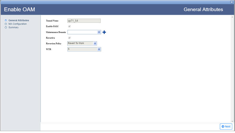
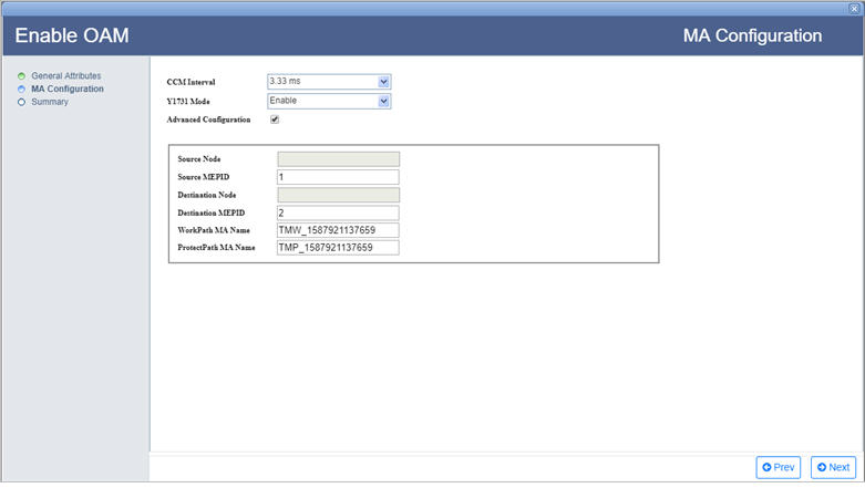
Action: Enable OAM
NOTE 1: The user cannot enable OAM on a tunnel in Orphan or Conflict state.
NOTE 2: Enable OAM option is available on unprotected tunnels and Disable OAM option on protected tunnels.
Perform the following steps to enable OAM on selected tunnel on which OAM is not enabled:
Action: Disable OAM
Action: Trigger LBM/LTM
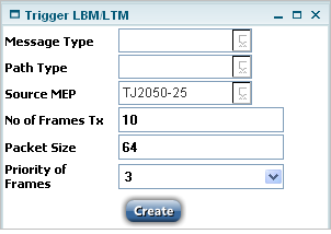
NOTE: If you select the message type as LTM, then the fields "No. of Frames Tx", "Packet Size", and "Priority of Frames" are not visible.
Trigger LBM/LTM parameters
Parameter |
Description |
|---|---|
Message Type |
Allows you to select the message type as LBM (Loop Back Message) or LTM (Link Trace Message). |
Path Type |
Allows you to select the path type as work path or the protect path. |
Source MEP |
Allows you to select the MEP from where the LBM triggered. |
No. of Frames Tx |
Allows you to edit the count of frames to be transmitted. |
Packet Size |
Allows you to edit the size of LBM frames. |
Priority of Frames |
Allows you to select the priority of the frames. |
Action: Trigger External Command
NOTE: The external command is valid only for the protected tunnels in active state. This feature is not supported on every node type present in the TJ5500.
Perform the following steps to trigger an external command:

NOTE: In G.8031 mode, the external command "Manual Switch to Work" is supported for non-revertive tunnels.
View LBM/LTM Parameters
To view the parameters of LBM/LTM,
LBM/LTM Parameters
Parameter |
Description |
|---|---|
LbmState |
Displays the state of loopback message. |
LbmResult |
Displays the result of loopback message. |
Lbm FramesTx |
Displays the number of LBM Tx count. |
Lbm FramesRx |
Displays the number of LBM Rx count. |
Lbm Frames Invalid |
Displays the number of LBM frames that are invalid. |
LbrAvgRTT(usecs) |
Displays the round trip time of LBR average/minimum/maximum. |
LbrMinRTT(usecs) |
|
LbrMaxRTT(usecs) |
|
LtmState |
Displays the LTM present status. If triggered - the status is "in progress"; else - idle. |
Ltm Frames Tx |
Displays the number of LTM Tx count. |
Ltm Frames Rx |
Displays the number of LTM Rx count. |
Ltm Frames Invalid |
Displays the number of LTM frames that are invalid. |
Ltm Result Path |
Displays the LTM result path. |
Action: Add Protection to Tunnel
NOTE: Add Protection is supported for only MPLS-TP tunnels in Active state and to only tunnels where the parameter 'Support Adding Protection' is enabled while creating tunnel.
Perform the following steps to add protection to the selected tunnel:
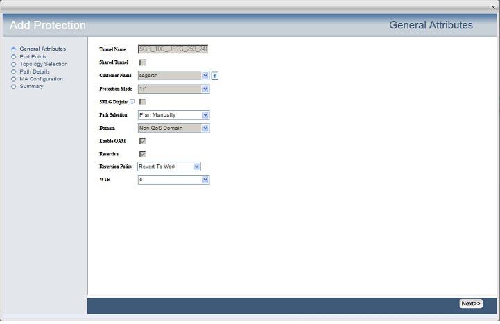
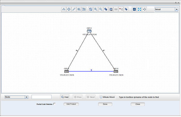
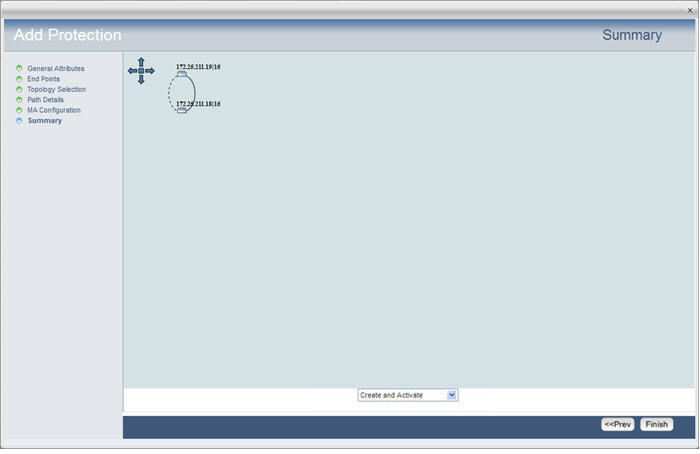
When the selected tunnel is in pending state only Create option is available.
Action: Trigger LSP Ping/Trace Route
To trigger LSP Ping/Trace Route, the tunnel has to be in the provisioned state in MPLS-TP mode.
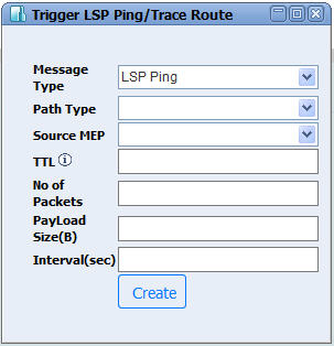
Trigger LSP Ping/Trace Route parameters
Parameter |
Description |
|---|---|
Message Type |
Allows you to select the message type as LSP Ping or LSP Trace Route. |
Path Type |
Allows you to select the path type as work or protect. |
Source MEP |
Allows you to select the MEP from where the LSP Ping is triggered. |
TTL |
Enter the Time-To-Live value for the packet to be sent to the network. Acceptable value is 1 to 255. |
No of Packets |
Enter the number of packets to be transmitted. It cannot be a non numeric value. |
PayLoad Size |
Enter the payload size. Valid range is from 64 to 512. |
Interval |
Enter the value for LSP ping interval. |
CFM Request Parameters
Parameter |
Description |
|---|---|
LSP Ping Status |
Displays the status of the ping message sent. |
LSP Ping Avg RTT |
Displays the round trip time of LSP Ping (average/maximum/minimum). |
LSP Ping Max RTT |
|
LSP Ping Min RTT |
|
LSP Ping No of Rx packets |
Displays the number of LSP Ping packets received. |
LSP Ping No of Tx packets |
Displays the number of LSP Ping packets transmitted. |
LSP Ping Pay load size |
Displays the size of packet sent for ping. |
LSP Trace Route Status |
Displays the status of the trace route message sent. |
LSP Trace Route Result |
Click Show Trace Route Path to view the result under the tab Tunnel Path. |
NOTE: Trigger action is only applicable for active Tunnels in MPLS mode.
The user is required to select Enable auto refresh option to display the CFM Request parameters and values.
"LSP Trace Route Status" and "LSP Trace Route Result" are displayed only when LSP Trace Route option is selected as the Message Type.
Action: Edit Customer
On detailed page of a tunnel, the parameter Shared Tunnel will be displayed as True if 'Shared Tunnel' check box was selected during tunnel creation; else it will displayed as False.
Perform the following steps to edit customer details for the selected tunnel:
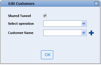
Action: Edit Tunnel path
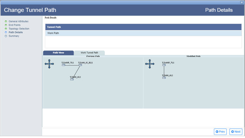
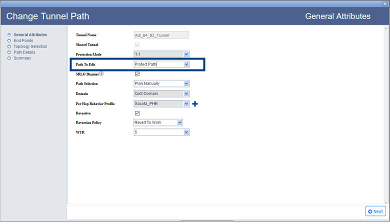
Perform the following steps to edit tunnel path:
NOTE: Tunnel edition cannot be performed on a tunnel in conflict or orphan state.
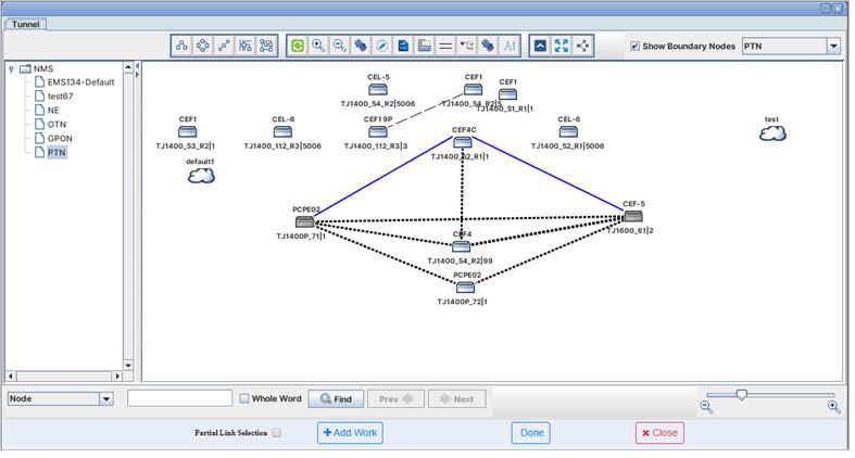
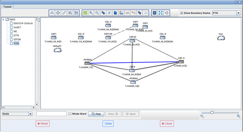
Present work/protect path of the selected tunnel will be highlighted in blue color as shown in the figure:
NOTE: Work path will be shown in solid line and protect path will be shown in dotted line.
