MPLS service/pseudowire is always created over tunnel. Hence, creation of tunnel between two switches is must before configuring any MPLS-TP service over it.
Perform the following steps to create a new tunnel in MPLS-TP domain:
> To create the tunnel in unprotected mode, select the Protection Mode as 'None'. Select Support Adding Protection check box to add protection later, if desired.
> To create the tunnel in protected mode, select the Protection Mode as '1:1'.
> To create the tunnel in Non Qos Domain, select the Domain as 'Non Qos Domain'.
> To create the tunnel in Qos Domain, select the Domain as 'Qos Domain' and the Per Hop Behavior Profile from the drop down list.
> To create the tunnel in any of the two domains, select the Domain as 'All Domain'.
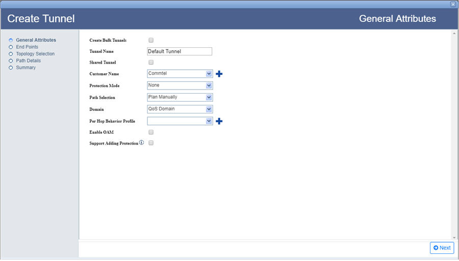
General Attributes parameters
Parameter |
Description |
Default Value |
Acceptable Values |
|---|---|---|---|
Create Bulk Tunnels |
Select the check box to create more than one tunnel. |
-- |
-- |
Tunnel Count |
Enter the number of tunnels desired to create |
|
|
Tunnel Name Prefix |
Enter a name for the tunnel. Tunnel name should begin with an alphabet. |
Default Tunnel |
|
Shared Tunnel |
Select the check box if the tunnel being created is desired to be shared with different customers. |
-- |
-- |
Customer Name |
Select the name of a customer from the options available in drop down list; or to create a new customer, click NOTE: Customer Name parameter will not be available when Shared Tunnel check box is selected. |
custName |
|
Protection Mode |
Select the mode of protection for the tunnel. NOTE: On selecting 1:1 option, Enable OAM check box gets selected by default; MA Configuration are added to the steps of tunnel creation on left panel of the General Attributes window. |
None |
|
SRLG Disjoint |
Select the check box to ensure that the work and protect paths selected are mutually link SRLG disjoint. The check box will be selected by default. This parameter is displayed when the Protection Mode parameter is set as 1:1. |
-- |
-- |
Path Selection |
Allows you to select the path of the tunnel being created, either manually or in auto discover mode. User needs to find the path manually if the same link is desired to be selected for both work and protect tunnels. NOTE: On selecting Auto Discover option, the Topology Selection step is replaced by Exclude Data on left panel of the General Attributes window. |
Plan Manually |
|
Domain |
Select the domain for the tunnel being created. |
Qos Domain |
|
Per Hop Behavior Profile |
Select the PHB profile from the drop down list; or to create a new profile, click NOTE: This option is available only when the Domain is selected as 'Qos Domain'. |
-- |
-- |
Enable OAM |
Select the check box to enable OAM on the tunnel. NOTE: On selection, MA Configuration are added to steps of tunnel creation on left panel of the General Attributes window. |
-- |
-- |
Maintenance Domain |
Select the maintenance domain level from the options available in drop down list; or to create a new maintenance domain, click |
-- |
User provisioned Maintenance Domain available as drop down options |
Revertive |
Select the check box to allow the traffic to automatically switch back to work or higher priority tunnel once the fault is rectified. |
-- |
-- |
Reversion Policy |
Select the desired option from the drop down menu. NOTE: This option is available only when the Revertive check box is selected. |
Revert to Work |
|
WTR |
Select the required wait-to-time restore. NOTE: This option is available only when the Revertive check box is selected. |
5 |
5 to 12 |
Support Adding Protection |
Select the check box to add protection later to the unprotected tunnel being created. NOTE: Support Adding Protection parameter will not be available if the Protection Mode is selected as 1:1. |
-- |
-- |
There are two ways of searching the desired node as follows:
> Enter the IP address/user label of the node in the text box provided and click ![]() (Search Node by IP Address or UserLabel). Or,
(Search Node by IP Address or UserLabel). Or,
> Click ![]() (Add switches using map view). Select desired NEs from the Topology selection window launched. Click Done.
(Add switches using map view). Select desired NEs from the Topology selection window launched. Click Done.
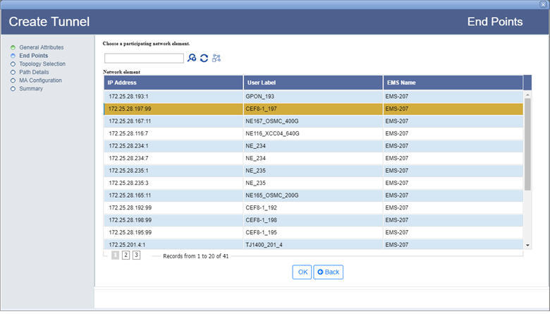
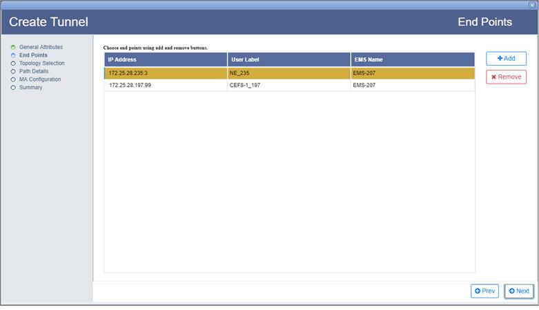
End Points parameters
Parameter |
Description |
|---|---|
Choose a participating network element |
|
|
Search Node by IP Address or UserLabel button allows you to search the node from the network element list. Enter the IP address or user label of the desired node in the text box provided and click this button. |
|
Load all nodes button reloads all the nodes in network element list. |
|
Add switches using map view button allows you to select the switches from the topology selection window. |
Choose end points using add and remove buttons |
|
IP Address |
Displays the IP address of the selected nodes. |
User Label |
Displays the node name which is assigned on the node where the switch is present. |
EMS Name |
Displays the name of the EMS in which the node is present. |
Add |
Allows the user to add end points for the creation of tunnel. Only two end points are required to be added for creating a tunnel. |
Remove |
Allows the user to remove the selected end points added for tunnel creation. |
(i) Direct Path Selection: This option is used for direct path selection between two end points with no intermediate nodes in path.
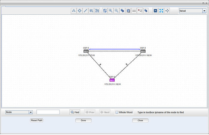
If the 'Protection Mode' is selected as None in the General Attributes page, select a direct path/link between the two selected end points (highlighted in black) and click Add Work. The tunnel path is added and the link color changes from pink to blue. Click Done.
If the 'Protection Mode' is selected as 1:1 in the General Attributes page, select a direct path/link and click Add Work. Select another direct path/link between same two end points and click Add Protect. The protect path is added and represented in blue dashed line. Click Done.
The following diagram shows work path selected by direct path selection method:
(ii) Partial Link Selection: This option is used when the user has to add more than one link to create a tunnel path between the two end points. Select the Partial Link Selection check box.
If the 'Protection Mode' is selected as None in the General Attributes page, select the paths/links between the two highlighted end points connecting the intermediate nodes and click Add Links. The path/link gets highlighted in cyan color. Click Add Work. The work tunnel path is added and the link color changes from cyan to blue. Click Done.
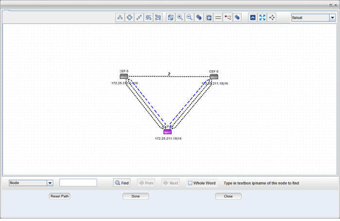
If the 'Protection Mode' is selected as 1:1 in the General Attributes page, select the paths/links and click Add Links > Add Work. Select Partial Link Selection check box again. Select the paths/links between the two highlighted end points connecting the intermediate nodes and click Add Links > Add Protect. The protect path is added and represented in blue dashed line. Click Done.
The following diagram shows protect path selected by partial link selection method:
The path/link between two end points can also be selected by both direct path method and partial link selection i.e. work by direct and protect by partial and vice versa.
The Reset Path button allows the user to reset the selected path and restart the path addition again.
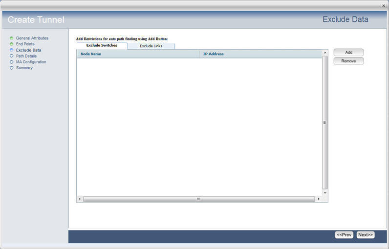
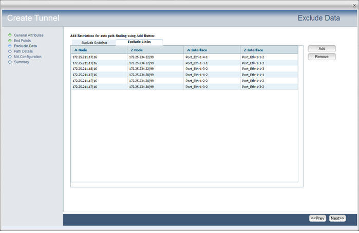
Exclude Data window is displayed instead of Topology Selection only when Path Selection is set as 'Auto Discover' in the General Attributes page.
The Path Details window in tunnel creation procedure is displayed when Protection Mode is selected as 1:1 on General Attributes page.
The Path Details window illustrates the details of the tunnel paths added in the Topology Selection step. Under Tunnel Path, select either Work Path or Protect Path to view its graphical representation under Path View tab and the details of selected tunnel path in tabular form under Tunnel Path tab. Click Next.
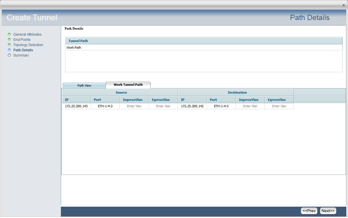
Path Details parameter
Parameter |
Description |
|---|---|
Work Path |
Select to display the details of tunnel work path. |
Protect Path |
Select to display the details of the tunnel protect path. |
Path View |
Select the tab to view the graphical representation of the Work/Protect path selected. |
Tunnel Path |
Select the tab to view the details of the selected path in tabular form. Source
Destination
|
The MA Configuration window in tunnel creation procedure is displayed only when Protection Mode is selected as '1:1' and/or Enable OAM check box is selected on General Attributes page.
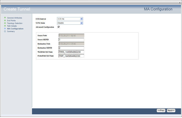
MA Configuration parameters
Parameter |
Description |
Default Values |
Acceptable Values |
|---|---|---|---|
CCM Interval |
Select the continuity check message time interval from the drop down list. |
3.33 ms |
|
Y1731 Mode |
Allows the user to enable or disable performance monitoring. |
Disable |
|
Advanced Configuration |
Select the check box to display the following given parameters. |
-- |
-- |
Source Node |
Displays the name of the source node. |
-- |
-- |
Source MEPID |
Allows you to enter the Source ID for the Maintenance End Points. |
1 |
1 to 8191 |
Destination Node |
Displays the name of the destination node. |
-- |
-- |
Destination MEPID |
Allows you to enter the Destination ID for the Maintenance End Points. |
2 |
1 to 8191 |
WorkPath MA Name |
Displays the name given to the work path MA. |
-- |
Alphanumeric characters |
ProtectPath MA Name |
Displays the name given to the protect path MA. |
-- |
Alphanumeric characters |
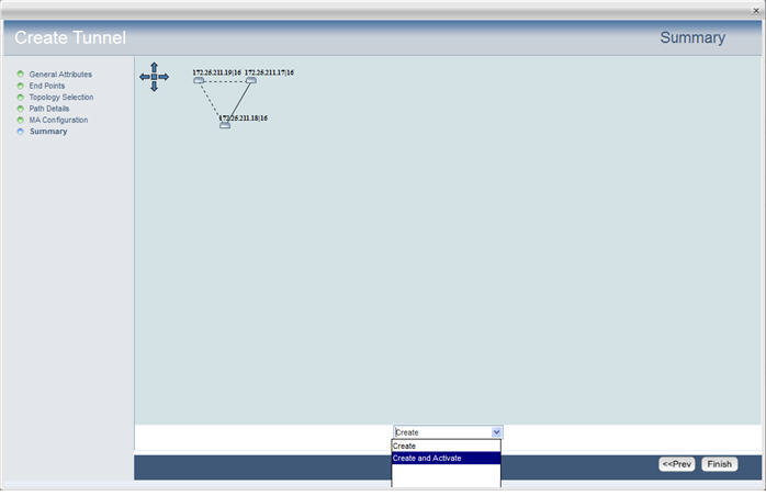
On Summary page of Create Tunnel, the end points with the connecting tunnel is displayed. The work path is represented in solid line and protect path in dashed line.
The following figure shows summary of a unprotected tunnel:
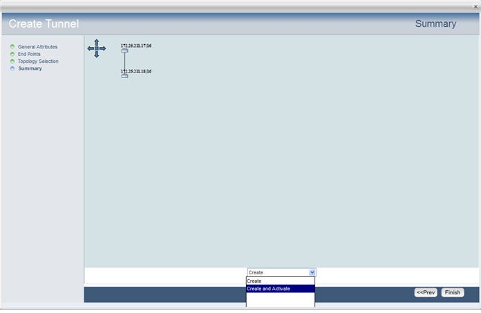
The following figure shows summary of a protected tunnel with one work (direct path) and one protect (partial link) path.
