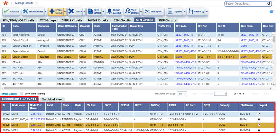
To view the attributes of a circuit i.e. the complete information of the circuit, graphical view and route details of a circuit do the following steps:
To view Circuit Attributes,
NOTE: Viewing circuit attributes is not allowed while the tabular view is grouped. Un-group the tabular view before performing the operation.

To view the route details,
Click Route Details. The route details of the circuit are displayed at the bottom of the Manage Circuits page.

Route Details Parameters
Attribute |
Description |
|---|---|
ID |
Displays the ID assigned to the circuit. |
Node Name |
Displays the name of the node. |
Node IP or Name |
Displays the IP of the node. |
Label |
Displays the label of the node. |
State |
Displays the circuit state:
This state is updated based on the SNC state of the circuit. |
Mode |
Displays the mode. |
SW Port |
Displays the source port of the work path. |
SWTS |
Displays the source timeslot of the work path. |
SP Port |
Displays the source port of the protect path. |
SPTS |
Displays the source timeslot of the protect path. |
DW Port |
Displays the destination port of the work path. |
DWTS |
Displays the destination timeslot of the work path. |
DP Port |
Displays the destination port of the protect path. |
DPTS |
Displays the destination timeslot of the protect path. |
Capacity |
Displays the capacity of the circuit. |
Ems Name |
Displays the name of the EMS. |
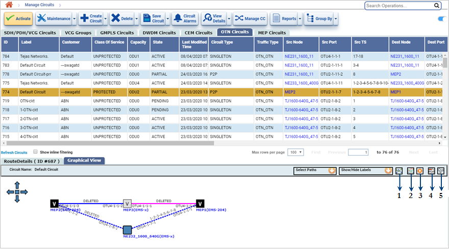
To view the topology of the circuit,

The following table provides the icons marked in the above image of the Graphical view tab.
Graphical view icons
Number |
Icon |
Represents |
|---|---|---|
1 |
|
Rearrange the Graph |
2 |
|
Active Path Display |
3 |
|
Alarms for the selected path |
4 |
|
Export Graphical View to PDF |
5 |
|
Show Graphical View In Topology |
The option Show/Hide Labels allows the user to view:
The option Select Paths allows you to select the path type to view the circuit in the graphical view. By clicking either work path or protect path, you can view the path highlighted in pink color in the graphical view.
If you have moved the graph to different position on Graphical View window and you to move to default position then click on ![]() (Rearrange the Graph)
(Rearrange the Graph)
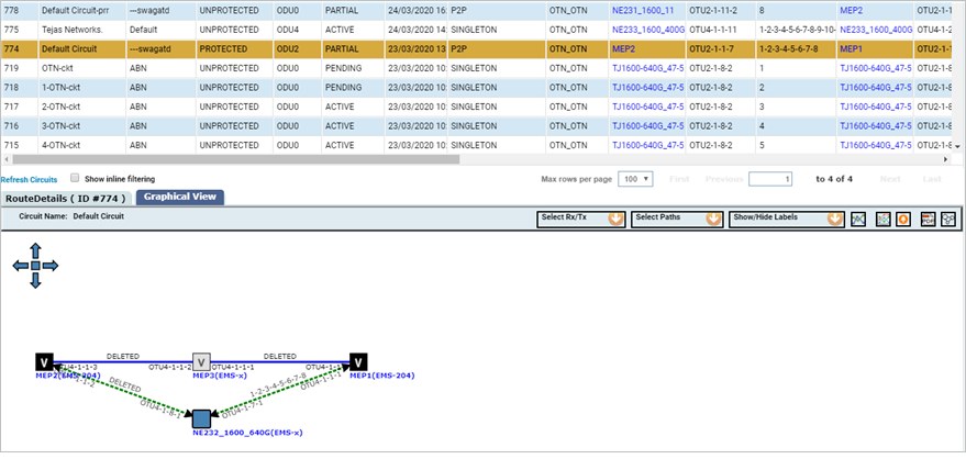
To view the active path click ![]() (Show Active Path from Source to Destination) icon in the Graphical View window.
(Show Active Path from Source to Destination) icon in the Graphical View window.
The following figure displays the traffic flowing in the active work path. The active path is indicated in green color. The arrow mark in the graphical view indicates the direction of traffic flow.

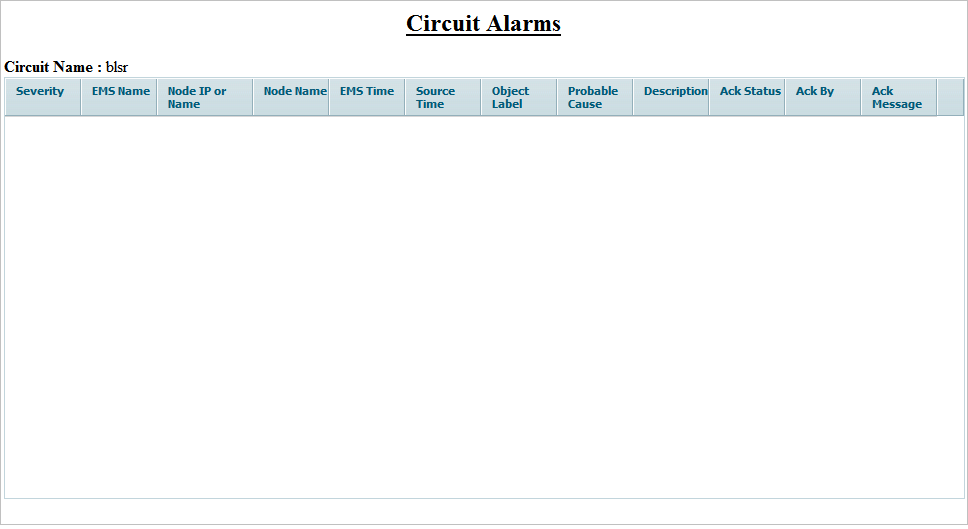
To view the active alarms on the circuit click ![]() (Show Alarms on selected Path) icon in the Graphical View window. The Circuit Alarms page is displayed in a different browser window.
(Show Alarms on selected Path) icon in the Graphical View window. The Circuit Alarms page is displayed in a different browser window.

To export the circuit information, route details, and graphical view of circuit to PDF format and save it to the local system click ![]() (Export Graphical View to PDF) in the Graphical View window. Choose the location in your local PC to save the PDF.
(Export Graphical View to PDF) in the Graphical View window. Choose the location in your local PC to save the PDF.
To view the graphical view in Topology View page ensure the Topology View page is open and click ![]() (Show Graphical View In Topology) icon in the Graphical View window. Open the Topology View page The desired circuit and the nodes present in the circuit will be shown highlighted (in blue) in the Topology View page.
(Show Graphical View In Topology) icon in the Graphical View window. Open the Topology View page The desired circuit and the nodes present in the circuit will be shown highlighted (in blue) in the Topology View page.
To view the intended paths for GMPLS ciruits, click on Show Intended Circuit icon which which shows the original assigned path. This icon is supported only for GMPLS circuits.