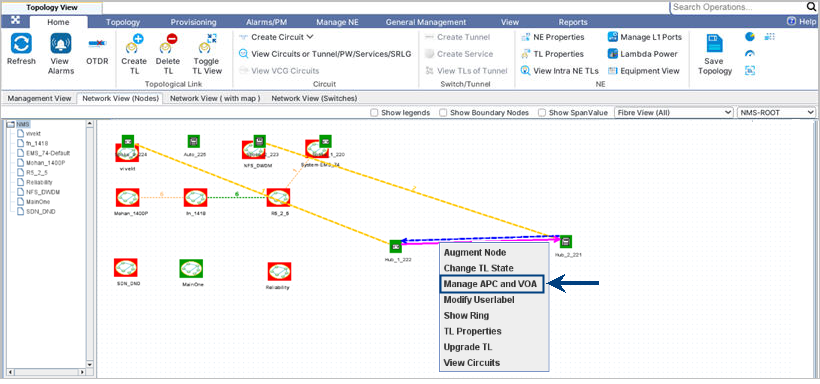
Perform the following steps to manage VOA (Variable Optical Attenuator) and APC (Automatic Power Control) in Topology View page. This procedure explains to enable APC on individual channels in ROADM/VOA.
NOTE: VOA is not supported for this release.
To view the graphical view of circuits in Topology View page, the Topology View page must be launched in a separate browser tab else error message is displayed.


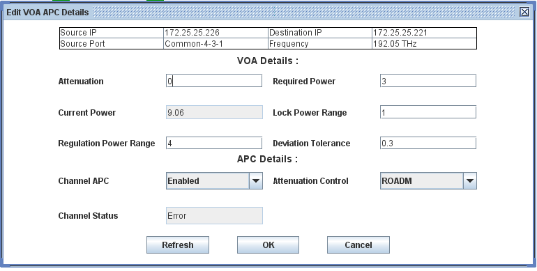
Edit VOA APC details
Attribute |
Description |
|---|---|
Attenuation |
Set the attenuation value in the range 0 to 15. |
Required Power |
Enter the channel power to be achieved after attenuation adjustment. The acceptable value is -15 to +15. |
Current Power |
Displays the present channel power. |
Lock Power Range |
Maximum tolerated power deviation before triggering APC. The acceptable value is -1 to +1. |
Regulation Power Range |
Range of Channel power deviation where power is adjusted. The acceptable value is -4 to +4. |
Deviation Tolerance |
Control loop continues to adjust the channel power level till the Tolerance range from -1 to +1. |
Channel APC |
Enable or disable the APC on the desired channel. |
Attenuation Control |
Select the device/card on which APC is required. The acceptable values are 'ROADM' or 'VOA'. NOTE: VOA option is not supported for this release. |
Channel Status |
Displays the current status of the channel. |