Perform the following steps to create an end to end ELine CEM service:
> To disable OAM on the service, select OAM as 'None' from drop down menu.
> To enable OAM on the service, select OAM as 'BFD Config'. Select the BFD Configuration parameters displayed.
> To enable PWSM on the service, select OAM as 'Pw Status'.Select the Pw Status Configuration parameters displayed.
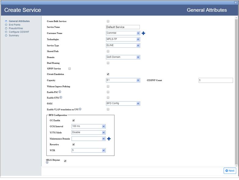
Refer General Attributes parameters table in the topic Create MPLS-TP service for description of parameters on General Attributes page.
There are two ways of searching the desired node from the list as follows:
> Enter the IP address/user label of the NE in the text box provided and click ![]() (Search Node by IP Address or UserLabel). Or,
(Search Node by IP Address or UserLabel). Or,
> Click ![]() (Add switches using map view) and select desired NEs from the Topology selection window launched. Click Done.
(Add switches using map view) and select desired NEs from the Topology selection window launched. Click Done.
To view the used VLAN range, select the port and click Show Used VLans. View Used VLAN Range(s) window is displayed with a list of used VLAN values for the selected port.
To view the bandwidth utilization, click View BW. View Port BW Utilization window is displayed with the bandwidth utilization details of Ingress and Egress Port.
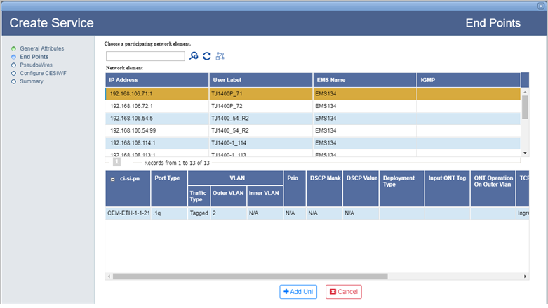
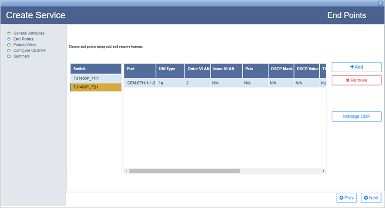
End Points parameters
Parameter |
Description |
|
|---|---|---|
Choose a participating network element. |
||
|
Search Node by IP Address or UserLabel button allows you to search the node from the network element list. Enter the IP address or user label of the desired node in the text box provided and click this button. |
|
|
Load all nodes button reloads all the nodes in network element list. |
|
|
Add switches using map view button launches the topology selection window that allows you to select the end points for service creation. |
|
Network element |
||
IP Address |
Displays the IP address of the node. |
|
User Label |
Displays the node label. |
|
EmsName |
Displays the EMS name in which the given node is present. |
|
IGMP |
Parameter not applicable. |
|
ci-si-pn |
Displays the shelf index, slot index and port number. |
|
Port Type |
Displays the port type. |
|
VLAN
|
Traffic Type |
Allows you to select the traffic type to enter the VLAN values. |
Outer VLAN |
Enter the VLAN ID. Acceptable value range from 1 to 4094 or 1 to 212 -1. |
|
Inner VLAN |
Parameter not applicable, hence displays N/A. |
|
Prio |
Displays the priority. Parameter not applicable, hence displays N/A. NOTE: CEM service can be created only in Qos Domain over STRICT priority Queues (CoS). |
|
DSCP Mask |
The mask assigned for Differentiated Services Code Point (DSCP) field. |
|
DSCP Value |
The Differentiated Services Code Point (DSCP) value defined for DEI bit. |
|
TCProfile |
Displays the TCP assigned on UNIs according to the capacity and count of CESIWFs. |
|
COS |
Allows to select an identifier for the default CoS queue to which the packet is assigned. Acceptable value ranges from 0 to 7. |
|
Priority Mapping Profile |
Displays the priority mapping profile associated with the switch, if any; else N/A is displayed. |
|
DSCP Mapping Profile |
Displays the DSCP mapping profile associated with the switch, if any; else N/A is displayed. |
|
IGMP |
Parameter not applicable. |
|
Choose end points using add and remove buttons. |
||
Switch |
Displays the switch IP address of the selected end point. |
|
Port |
Displays the UNI port selected on the given end point. |
|
UNI Type |
Displays the type of switching protocol of the user network interface. |
|
Outer VLAN |
Displays the selected VLAN ID. |
|
Inner VLAN |
Parameter not applicable, hence displays N/A. |
|
Prio |
Displays the priority for VLAN+PRIO port. |
|
DSCP Mask |
The mask assigned for Differentiated Services Code Point (DSCP) field. |
|
DSCP Value |
The Differentiated Services Code Point (DSCP) value defined for DEI bit. |
|
TCProfile |
The appropriate TCP will be assigned on UNIs according to the capacity and count of CESIWFs. |
|
COS |
Displays the selected identifier for the default CoS queue to which the packet is assigned. |
|
Priority Profile |
Displays the priority mapping profile. |
|
DSCP Mapping Profile |
Displays the DSCP mapping profile associated with the switch, if any; else N/A is displayed. |
|
Igmp Profile |
Displays the IGMP mapping profile associated with the switch, if any; else N/A is displayed. |
|
Add |
Add end point button allows the user to add nodes for the creation of end points. |
|
Remove |
Remove selected end point button allows the user to remove the selected node chosen for end points creation. |
|
Manage CDP |
Manage CDP button allows the user to associate the UNI ports with a capacity distribution profile. |
|
The PseudoWires page of Create Service provides the options to add or remove protection, selection of pseudowire path manually or automatic path detection, and MA configuration.
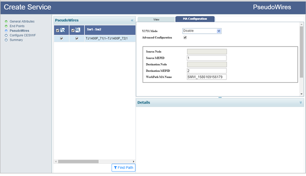
To find path for the pseudowire automatically,
Graphical representation of the pseudowire detected automatically is displayed under the View tab as shown in the following figure. Details of work path, protect path, excluded switches, and excluded tunnels is available under Details:
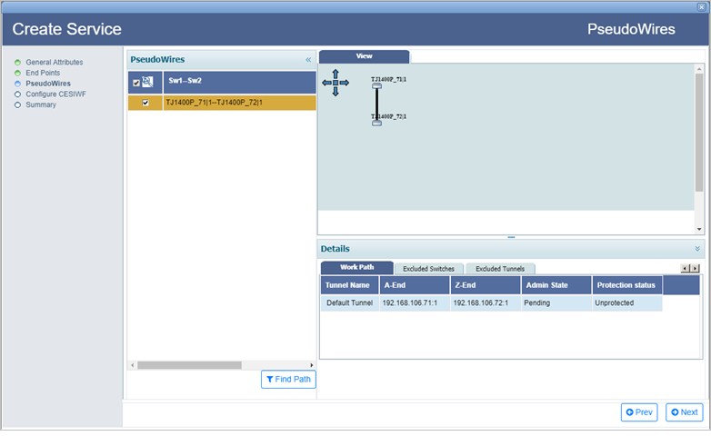
NOTE: When finding the pseudowire path automatically, the user is provided an option to exclude switches/tunnels. Select Excluded Switches and Excluded Tunnels tab. Click Add button and select the desired nodes and/links. Click Exclude Nodes or Exclude Links followed by Done. Remove button can be used to delete the added data. Select Find Path. Pseudowire path is calculated once again, excluding the selected switches/tunnels in the path.
To find path for the pseudowire manually,
(i) Direct Path Selection: This option is used for direct path selection between two end points with no intermediate nodes in between.
Select a direct path/link between the two selected end points (highlighted in black) and click Add Work. The pseudowire path is added and the link color changes from pink to blue. To add protection (if ![]() (Protection) check box was checked), select another path/link and click Add Protect.
(Protection) check box was checked), select another path/link and click Add Protect.
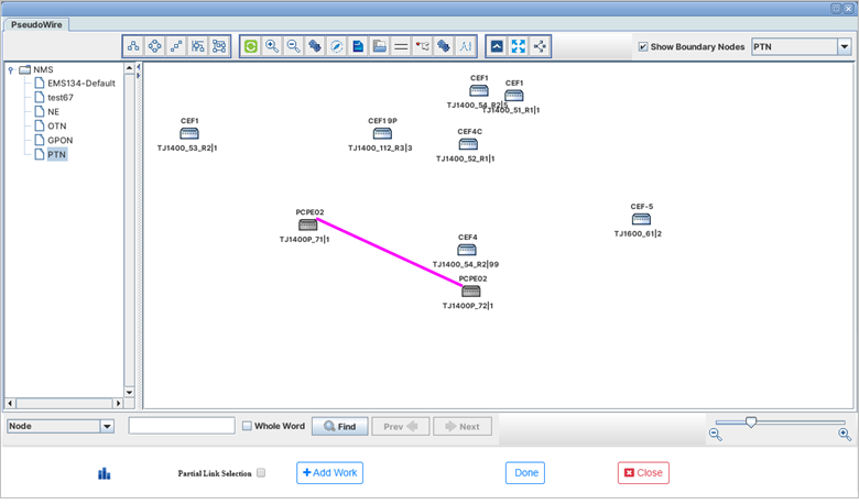
Click Done. The graphical representation of the pseudowire added is displayed on the PseudoWires page under View tab along with work path and protect path details under Details column as shown in the following figure:
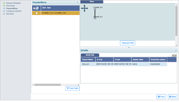
(ii) Partial Link Selection: This option is used when the user has to add more than one link to create a pseudowire path between the two end points.
Select the Partial Link Selection check box. Select the path/link and click Add link. Similarly, add the additional links between intermediate nodes connecting the two selected end points. The path/link gets highlighted in cyan color. Click the Add Work. The pseudowire path is added and the link color changes from cyan to blue. To add protection (if ![]() (Protection) check box was checked), select Partial Link Selection check box again (if desired) and select another path/link. Click Add Links > Add Protect. Click Done. In case path addition fails, the partial link selection will be reset.
(Protection) check box was checked), select Partial Link Selection check box again (if desired) and select another path/link. Click Add Links > Add Protect. Click Done. In case path addition fails, the partial link selection will be reset.
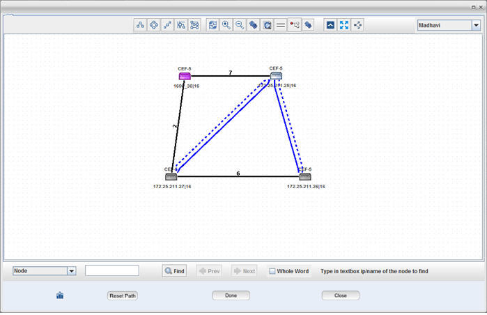
Graphical representation of the pseudowire added is displayed on the PseudoWires page under View tab along with work path details under Details column.
NOTE: An additional PW Status Info page will be displayed if OAM was selected as 'Pw Status' on General Attributes page. For more information refer to Step 4: PW Status Info in the topic Create MPLS-TP service with PWSM.
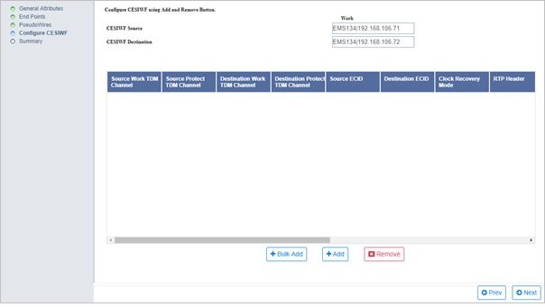
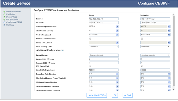
Uncheck the option if node endpoint is having CEF1. CESIWF protection is not supported on CEF1 cards. The user can also have protected CESIWF on one endpoint and unprotected endpoint on other end point.
To view and validate the ECID(s) for the selected port,
(i) Click Show Used ECIDs. View Used ECID page is displayed showing the used [existing and/or planned] ECID(s) and TDM Channel(s), if any.
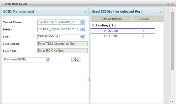
(ii) Select the required Network Element and the corresponding Switch followed by the Port.
(iii) Do one of the following:
> To view used ECIDs, select the action as Show used ECIDs from the drop down menu. The used ECID values for the selected port is displayed under the right column.
> To filter TDM channel, select the action as Filter TDM Channel from drop down menu and enter the port number in TDM Channel text box in ci-si-pn format. Click Go. A message will be displayed whether that TDM channel is free for use or not.
> To filter ECID, select the action as Filter ECID from drop down menu and enter the ECID number in ECID Value text box. ECID must be a number in range 1 - 1048575. Click Go. A message will be displayed whether the ECID is free for use or not.
(iv) Click Close to exit this window.
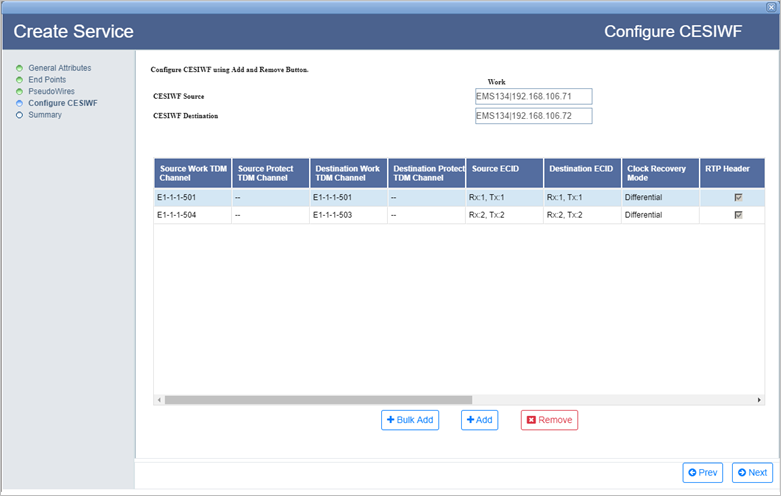
A parameter 'Select CESIWF for Circuit Creation' for automatic creation of logical CEM circuits is displayed while creating CEM services on TJ1400P node and CEM1 card. To enable the option click ![]() , check box will be displayed against each CESIWF pairs to select the CESIWF(s).
, check box will be displayed against each CESIWF pairs to select the CESIWF(s).
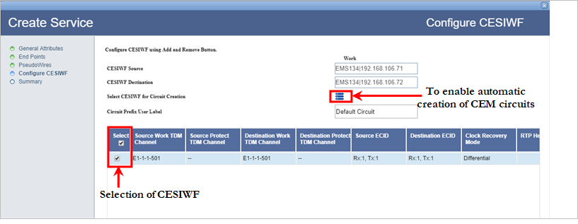
Configure CESIWF for Source and Destination parameters
Parameter |
Description |
Default Value |
Acceptable Values |
|---|---|---|---|
End Node |
Displays the node as defined for UNI. This field is not editable. |
-- |
-- |
Work TDM Channel |
Displays the TDM port which is emulated over Packet Network. |
-- |
List of TDM ports |
Enable CESIWF Protection |
Select the checkbox to enable CESIWF protection. |
-- |
-- |
Protect TDM Channel |
Displays the TDM port which is emulated over Packet Network. |
-- |
List of TDM ports |
Clock Recovery Mode |
Allows you to select the mode used to recover timing from packet side for transmitting towards TDM side. Differential is used only if the nodes at the end points of the CEM path are synchronized. |
Differential |
|
TDM Payload Size |
Allows you to enter the size of TDM payload data each CEM packet will carry. |
256 |
64 to 1498 |
Additional Configuration |
|||
Payload Format |
Displays the type of payload format. This field is not editable. |
Structure Agnostic |
Structure Agnostic |
Starting ECID |
Allows you to enter the Emulated Circuit Identifier in the transmit and receive side. |
-- |
1 to 1048575 |
RTP Header Used |
Allows you to select/unselect the RTP header in the CEM packets. |
true |
|
Jitter Buffer Depth (usec.) |
Allows you to enter the depth of Jitter Buffer which is used to smooth out bursty packets while sending towards TDM side. This is used to cancel out delay variation in the Packet Network. |
-- |
Valid range is 1000 to 100000 |
Frame Loss Ratio Threshold |
Threshold ratio of number of frames lost to number of frames expected. If it exceeds the configured value an alarm is raised. |
5% |
0-100% |
Miss Ordered Dropped Frames Threshold |
Threshold ratio of number of frames arrived late to number of frames expected for the configured period of time (2.5 s not available for editing). If it exceeds the configured value an alarm is raised. |
5% |
0-100% |
Malformed Frames Threshold |
Threshold ratio of number of frames that are malformed to number of frames expected for the configured period of time (2.5 s not available for editing). If it exceeds the configured value an alarm is raised. |
5% |
0-100% |
Jitter Buffer Overrun Threshold |
Ratio of number of frames that are not able to be accommodated in the jitter buffer to number of frames expected for the configured period of time (2.5 s not available for editing). If it exceeds the configured value an alarm is raised. |
5% |
0-100% |
Jitter Buffer Underrun Threshold |
Allows you to enter a value for the ratio of number of free time slots present in the buffer to the number of frames expected for the configured period of time (2.5 s not available for editing). If it exceeds the configured value, an alarm is raised. |
5% |
0-100% |
On Summary page of Create Service, the end points with the connecting pseudowire is displayed as shown in the following figure:
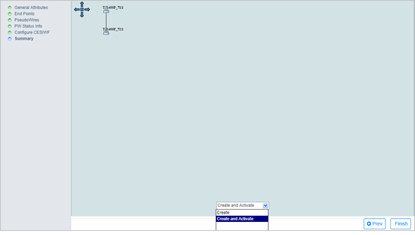
The service created act as CEM_Service_TL for TDM circuits.