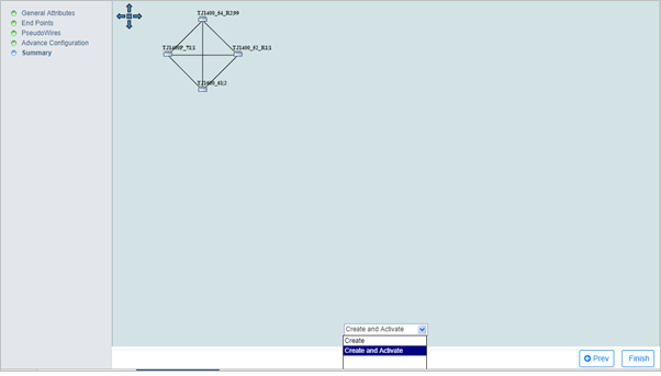
A Full mesh network is a type of service where the node participating in the network also acts as a relay for the other nodes.
Perform the following steps to create an ELAN full mesh service:
A series of new windows will now be displayed for step-by-step creation of the service.
> To create the service in Non Qos Domain, select the Domain as 'Non Qos Domain'.
> To create the service in Qos Domain, select the Domain as 'Qos Domain'.
> To create the service in any of the two domain, select the Domain as "All Domain'.
> To disable OAM on the service, select OAM as 'None' from drop down menu.
> To enable OAM on the service, select OAM as 'BFD Config'. Select the BFD Configuration parameters displayed.
> To enable PWSM on the service, select OAM as 'Pw Status'. Select the PW Status Configuration parameters displayed.
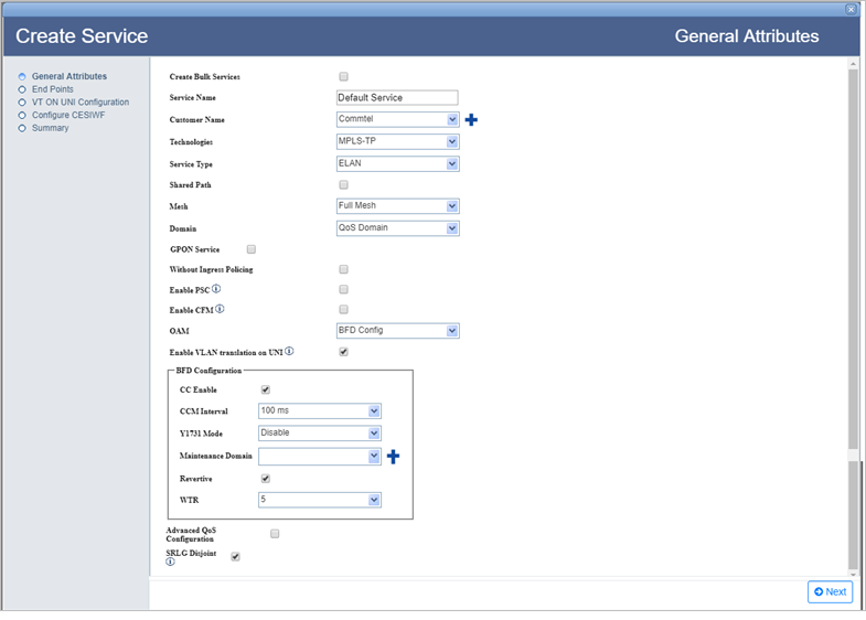
General Attributes parameters
Parameter |
Description |
Default Value |
Acceptable Values |
|---|---|---|---|
Service Name |
Enter a name for the service. Service name should begin with an alphabet. |
Default Service |
|
Customer Name |
Select the name of the customer from the options available in drop down list; or to create a new customer, click |
custName |
|
Technologies |
Select the type technology for service creation. |
MPLS-TP |
|
Service Type |
Select the type of service to be created. |
ELAN |
|
Shared Path |
Select the check box if the service being created is desired to be shared with different customers. |
-- |
-- |
Mesh |
Select the type of ELAN service from the drop down list desired to create. NOTE: This parameter is displayed when the Service Type is selected as ELAN. |
Full Mesh |
|
Domain |
Select the domain for the service being created. |
Qos Domain |
|
Enable PSC |
Select the check box to enable Protection State Coordination. On selection, OAM by default is set as BFD Config. |
-- |
-- |
OAM |
Select the desired option from the drop down list to enable or disable OAM on the service.
|
BFD Config |
|
Pw Status/BFD Configuration |
|||
Pw Status refresh Time |
Enter the refresh time for pseudowire status message. This parameter is displayed when OAM is set as Pw Status. |
600 |
1 to 65535 second |
CCM Interval |
Select the continuity check message time interval from the drop down list. This parameter is displayed when OAM is set as BFD Config. |
100 ms |
|
Y1731 Mode |
Standard defining OAM functions and mechanisms for Ethernet based networks. Allows the user to enable or disable performance monitoring. |
Disable |
|
Maintenance Domain |
Select the maintenance domain level from the options available in drop down list; or to create a new maintenance domain, click |
-- |
User provisioned Maintenance Domain available as drop down options |
Revertive |
Traffic is automatically switched back to the work path once the fault is rectified. Select the check box as desired. |
-- |
-- |
WTR |
Select the required wait-to-time restore from the drop down list. |
5 |
5 to 12 |
Advanced Qos Configuration |
Select the check box to enable advanced configuration on Qos. This parameter is displayed when Domain is set as Qos Domain. |
-- |
-- |
Allow CIR Traffic in ELAN |
Select the check box to enable the non 0 CIR value in the TCProfile list. NOTE: This parameter is displayed when the Advanced Qos Configuration check box is selected. |
-- |
-- |
SRLG Disjoint |
Select the check box to ensure that the work and protect paths selected are mutually link SRLG disjoint. The check box will be selected by default. |
-- |
-- |
There are two ways of searching the desired node explained as follows:
> Enter the IP address/user label of the node in the text box provided and click ![]() (Search Node by IP Address or UserLabel). Or,
(Search Node by IP Address or UserLabel). Or,
> Click ![]() (Add switches using map view). Select desired end points from the Topology selection window launched and click Done. Note that only one node can be added at a time.
(Add switches using map view). Select desired end points from the Topology selection window launched and click Done. Note that only one node can be added at a time.
> If Domain is selected as 'Non Qos Domain' or All Domain' in General Attributes page, enter the VLAN value only under First Tag column. For All Domain the UNI port can be associated with TCProfile and CoS-0.
> If Domain is selected as 'Qos Domain', enter the VLAN value under First Tag column and associate a Priority Mapping Profile or DSCP Mapping Profile or a pair of TCProfile and COS values.
To view the bandwidth utilization, select a port and click View BW. View Port BW Utilization window is displayed with the bandwidth utilization details of Ingress and Egress Port.
To view the used VLAN range, select a port and click Show Used VLans. View Used VLAN Range(s) window is displayed with a list of used VLAN values for the selected port.
NOTE: The user can add more than one Uni to an end point.
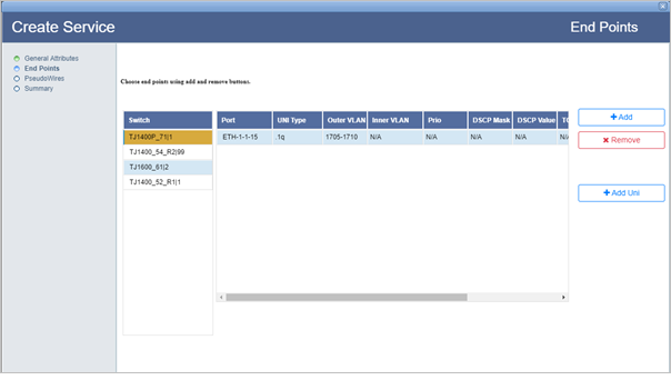
Finally all added endpoints and UNIs are displayed as shown in the following figure:
End Points parameters
Parameter |
Description |
|
|---|---|---|
Choose a participating network element. |
||
|
Search Node by IP Address or UserLabel button allows you to search the node from the network element list. Enter the IP address or user label of the desired node in the text box provided and click this button. |
|
|
Load all nodes button reloads all the nodes in network element list. |
|
|
Add switches using map view button launches the topology selection window that allows you to select the end points for service creation. |
|
Network element |
||
IP Address |
Displays the IP address of the node. |
|
User Label |
Displays the node label. |
|
EmsName |
Displays the EMS name in which the given node is present. |
|
IGMP |
Parameter not applicable. |
|
ci-si-pn |
Displays the shelf index, slot index and port number. |
|
Port Type |
Displays the port type. |
|
VLAN
|
All |
Allows you to select one or more VLANs by selecting the check box against the desired VLANs. |
First Tag |
Enter the VLAN ID. Acceptable value range from 1 to 4094 or 1 to 212 -1. |
|
Second Tag |
This parameter is applicable when VLAN type of port is .1ad with .1q. Then .1q VLAN is inner VLAN and .1ad VLAN is outer VLAN. |
|
Prio |
Displays the priority. |
|
DSCP Mask |
The mask assigned for Differentiated Services Code Point (DSCP) field. |
|
DSCP Value |
The Differentiated Services Code Point (DSCP) value defined for DEI bit. |
|
TCProfile |
Allows to select the TCProfiles created at the NMS. Acceptable values includes a list of TC Profiles created. |
|
COS |
Allows to select an identifier for the default CoS queue to which the packet is assigned. Acceptable value ranges from 0 to 7. |
|
Priority Mapping Profile |
Allows you to associate a priority mapping profile to the selected port from the drop down list. |
|
DSCP Profile |
Allows you to associate a DSCP mapping profile to the selected port from the drop down list. |
|
IGMP |
Parameter not applicable. |
|
Choose end points using add and remove buttons. |
||
Switch |
Displays the switch IP address of the selected end point. |
|
Port |
Displays the UNI port selected on the given end point. |
|
UNI Type |
Displays the type of switching protocol of the user network interface. |
|
First Tag |
Displays the selected VLAN ID. |
|
Second Tag |
Displays the selected VLAN ID when VLAN type of port is .1ad with .1q. |
|
Prio |
Displays the priority. |
|
DSCP Mask |
The mask assigned for Differentiated Services Code Point (DSCP) field. |
|
DSCP Value |
The Differentiated Services Code Point (DSCP) value defined for DEI bit. |
|
TCProfile |
Displays the TCProfile selected for the UNI port on a given end point. |
|
COS |
Displays the selected identifier for the default CoS queue to which the packet is assigned. |
|
Priority Profile |
Displays the priority mapping profile associated with the switch, if any; else N/A is displayed. |
|
DSCP Mapping Profile |
Displays the DSCP mapping profile associated with the switch, if any; else N/A is displayed. |
|
Igmp profile |
Parameter not applicable, hence displays N/A. |
|
Add |
Add end point button allows the user to add nodes for the creation of end points. |
|
Remove |
Remove selected end point button allows the user to remove the selected node chosen for end points creation. |
|
Add Uni |
Add unis to the selected end point button allows the user to add UNI ports to the selected end point. |
|
Remove Uni |
Remove unis from end point button allows the user to remove the selected UNI port from a given end point. |
|
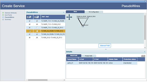
The PseudoWires page of Create Service provides the options to add or remove protection, selection of pseudowire path manually or automatic path detection, MA configuration, and Qos Configuration.
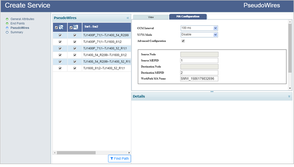
NOTE 1: CoS Value at UNI ports would be considered for bandwidth calculation only if bandwidth values for the CoS is not specified for the Pseudowire.
NOTE 2: Service creation will fail if the bandwidth defined in TCProfile attached to any UNI port in the service is not available on the port. The user can then manually assign the bandwidth value for CIR and PIR in Qos Configuration tab.
To find pseudowire path automatically,
Graphical representation of the pseudowire detected automatically is displayed under the View tab as shown in the following figure. Details of work and protect path, excluded switches and excluded tunnels are available under Details column:
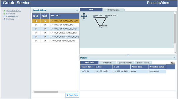
NOTE: When finding the pseudowire path automatically, the user is provided an option to exclude switches/tunnels. Select Excluded Switches and Excluded Tunnels tab. Click Add button and select the desired nodes and/links. Click Exclude Nodes or Exclude Links followed by Done. Remove button can be used to delete the added data. Select Find Path. Pseudowire path is calculated once again, excluding the selected switches/tunnels in the path.
To find pseudowire path manually,
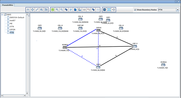
(i) Direct Path Selection: This option is used for direct path selection between two end points with no intermediate nodes in between and is applicable to both work and protect path.
Select a direct path/link between the two selected end points (highlighted in black) and click Add Work. The work path is added and the link color changes from pink to blue.
To add protection, select another direct path/link between the two selected end points and click Add Protect. The protect path is added and represented in blue dashed line.
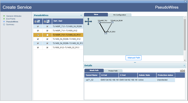
Click Done. Graphical representation of the pseudowire added is displayed on the PseudoWires page under View tab along with work and protect path details under Details column as shown in the following figure:
(ii) Partial Link Selection: This option is used when the user has to add more than one link to create a pseudowire path between the two end points and is applicable to both work and protect path.
Select the Partial Link Selection check box. Select the path/link and click Add link. Similarly, add the additional links between intermediate nodes connecting the two selected end points. The path/link gets highlighted in cyan color. Click the Add Work. The work path is added and the link color changes from cyan to blue solid line.
To add protection, select Partial Link Selection check box again. Select the path/link and click Add link. Similarly, add the other links between intermediate nodes connecting the selected two end points and select Add Protect. The protect path is added and represented in blue dashed line.
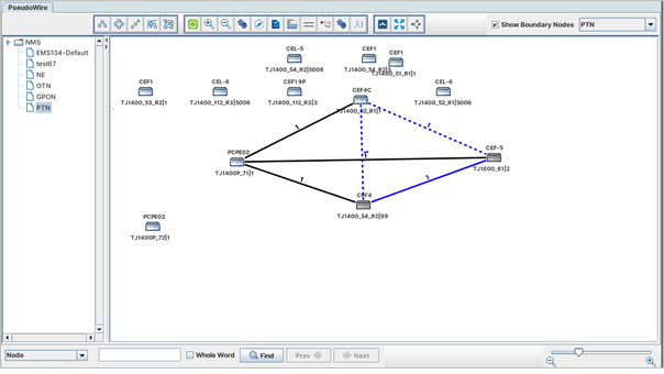
Click Done. In case path addition fails, the partial link selection will be reset.
Graphical representation of the pseudowire added is displayed on the PseudoWires page under View tab along with work and protect path details under Details column as shown in the following figure:
NOTE: An additional PW Status Info page will be displayed if OAM was selected as 'Pw Status' on General Attributes page. For more information refer to Step 4: PW Status Info in the topic Create MPLS-TP service with PWSM.
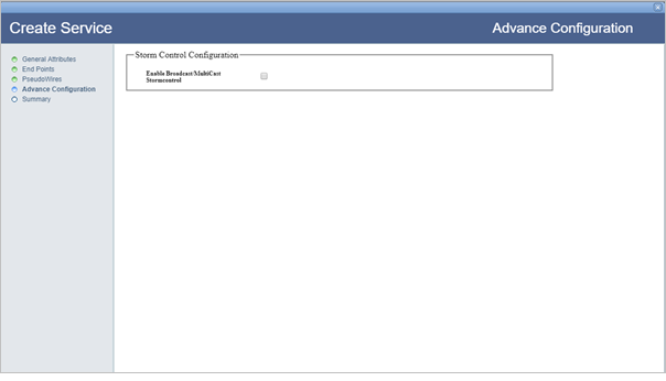
On Advance Configuration window, Storm Control Configuration is performed. Select the Enable Broadcast/MultiCast Stormcontrol check box if desired and then enter the BroadCast/Multicast Stormcontrol value in Mbps in the text box displayed. Click Next to view the summary of the ELAN service.
On Summary page of Create Service, the end points with the connecting pseudowire is displayed as shown in the following figure:
