TJ5500 supports the MEF standard services using .1q/.1ad. This section explains the procedure for simple .1q/.1ad service creation. GPON service and CEM service creation in .1q/.1ad is explained in detail in further sections.
Perform the following steps to create a new service using .1q/.1ad:
NOTE: Dual Homing and Enable LLF parameters are displayed only when the service type is selected as ELINE. Service Type should always be ELAN for broadcast storm control profile.
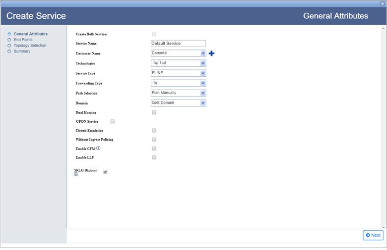
General Attributes parameters
Parameter |
Description |
Default Value |
Acceptable Values |
|---|---|---|---|
Create Bulk Service |
Bulk services creation is not supported for .1q/.1ad services. Hence do not select the check box. |
Check box disabled |
-- |
Service Name |
Enter a name for the service. |
DefaultService |
|
Customer Name |
Select the name of the customer from the options available in drop down list; or to create a new customer, click |
custName |
|
Technologies |
Select the type as .1q/.1ad technology for service creation. |
MPLS-TP |
.1q/.1ad |
Service Type |
Select the type of service to be created. |
ELINE |
|
Forwarding Type |
Select the forwarding type for the service. |
.1q |
|
Path Selection |
Allows you to select the path of the service being created, either manually or in auto discover mode. NOTE: On selecting Auto Discover option, the Topology Selection is replaced by Exclude Data step on left panel of the General Attributes window. |
Plan Manually |
|
Domain |
Select the domain for the service being created. |
Qos Domain |
|
Dual Homing |
Select the check box to create an ELINE Dual Homed Service. NOTE: On selecting Dual Homing check box, Backup Nodes is added to steps of service creation on left panel of the General Attributes window. |
Check box disabled |
-- |
GPON Service |
Not applicable. |
-- |
-- |
Enable CFM |
Select the check box to enable Continuity Fault Management (CFM). NOTE: On selecting Enable CFM check box, Advance Configuration and CFM Configuration is added to steps of service creation on left panel of the General Attributes window. |
-- |
-- |
Without Ingress Policing |
Select the check box if the ingress policing is not required for QoS service. |
-- |
-- |
Circuit Emulation |
Not applicable. |
-- |
-- |
Capacity |
Select the capacity from the drop down menu. |
E1/DS1 |
|
Enable LLF |
Select the check box to enable LLF (Link Loss Forwarding). LLF Configuration option is displayed. |
-- |
-- |
LLF Configuration |
|||
CC |
Enable the check box to verify the connectivity between two MEPs at regular intervals. |
||
CCM Interval |
Select the continuity check message time interval from the drop down list. This parameter is displayed when OAM is set as BFD Config. |
100 ms |
|
Maintenance Domain |
Select the maintenance domain level from the options available in drop down list; or to create a new maintenance domain, click |
-- |
List of options from drop down menu. |
SRLG Disjoint |
Select the check box to ensure that the work and protect paths selected are mutually link SRLG disjoint. The check box will be selected by default. |
-- |
-- |
There are two ways of searching the desired node from the list explained as follows:
> Enter the IP address/user label of the node in the text box provided and click ![]() (Search Node by IP Address or UserLabel). Or,
(Search Node by IP Address or UserLabel). Or,
> Click ![]() (Add switches using map view) and select desired NEs from the Topology selection window launched. Click Done.
(Add switches using map view) and select desired NEs from the Topology selection window launched. Click Done.
> If Domain is selected as 'Non Qos Domain' or 'All Domain' in General Attributes page, enter the VLAN value only for regular mode or select the check box under All column for Transparent mode. For All Domain the UNI port can be associated with TCProfile and CoS-0.
> If Domain is selected as 'Qos Domain', enter the VLAN value and associate a Priority Mapping Profile or DSCP Mapping Profile or a pair of TCProfile and COS values.
To view the bandwidth utilization, click View BW. View Port BW Utilization window is displayed with the bandwidth utilization details of Ingress and Egress Port.
To view the used VLAN range, click Show Used VLans. View Used VLAN Range(s) window is displayed with a list of used VLAN values for the selected port.
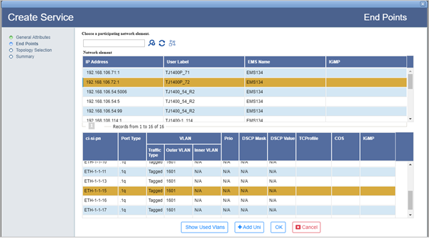
An ELine service must have two end points as shown in the following figure:
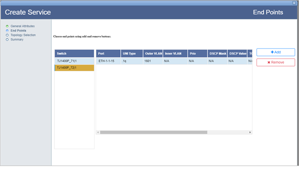
NOTE: If the Dual Homed check box is selected on General Attributes page for an ELINE service, then the Dual Homed check box has to be selected for one of the end point while adding the end points.
Refer End Points parameters table in the topic Create MPLS-TP service for description of parameters on End Points page.
Backup Nodes window is displayed when Dual Homed check box is selected on General Attributes page for an ELINE service. Click Add Backup and select the node and the UNI port. Click Add Uni and Ok. The backup node for the selected primary node gets added. Click Next. Topology Selection page is displayed.
> To automatically add the NNI(VLAN) value, select the Auto check box and click Add Path. When Auto NNI (VLAN) is checked, the NMS suggests the NNI(VLAN) value. The same VLAN ID for UNI will be copied to NNI.
> To manually add the NNI(VLAN) value, un-check the Auto check box and enter the NNI(VLAN) value. Click Add Path.
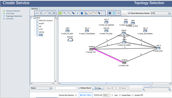
NOTE: If the user makes any changes in the general attributes, add UNIs or path selection mode; the added path will be deleted and Add Path option will replace Reset Path.
If the NNI Vlan value falls within the Data VID of a provisioned ring, the user will receive an alert message to check the Include Ring option else change the UNI/NNI Vlan Value or Path.
Exclude Data window is displayed instead of Topology Selection only when Path Selection is set as 'Auto Discover' in General Attributes page.
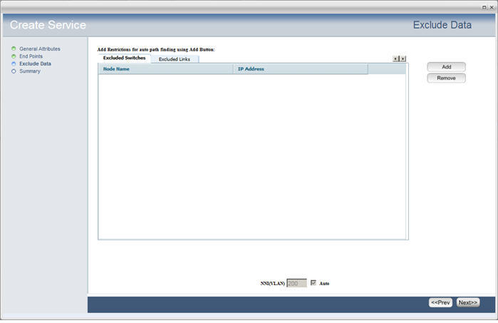
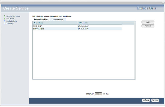
Advance Configuration window displayed when Enable LLF check box is selected in the General Attributes page. Enter the values against the desired attributes and click Next.
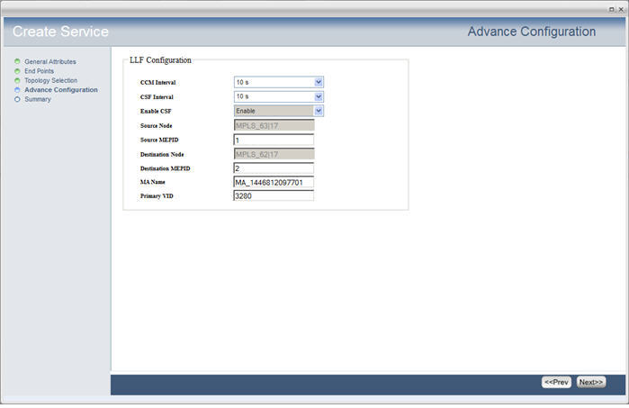
NOTE: An error will be displayed if LLF is not supported on the source and destination nodes.
Advance Configuration window is displayed when the Service Type is selected as 'ELAN' in the General Attributes page. To enable, select Enable Broadcast/MultiCast Storm Control check box and enter the BroadCast/Multicast Stormcontrol value in Mbps. The minimum value is 66Kbps.
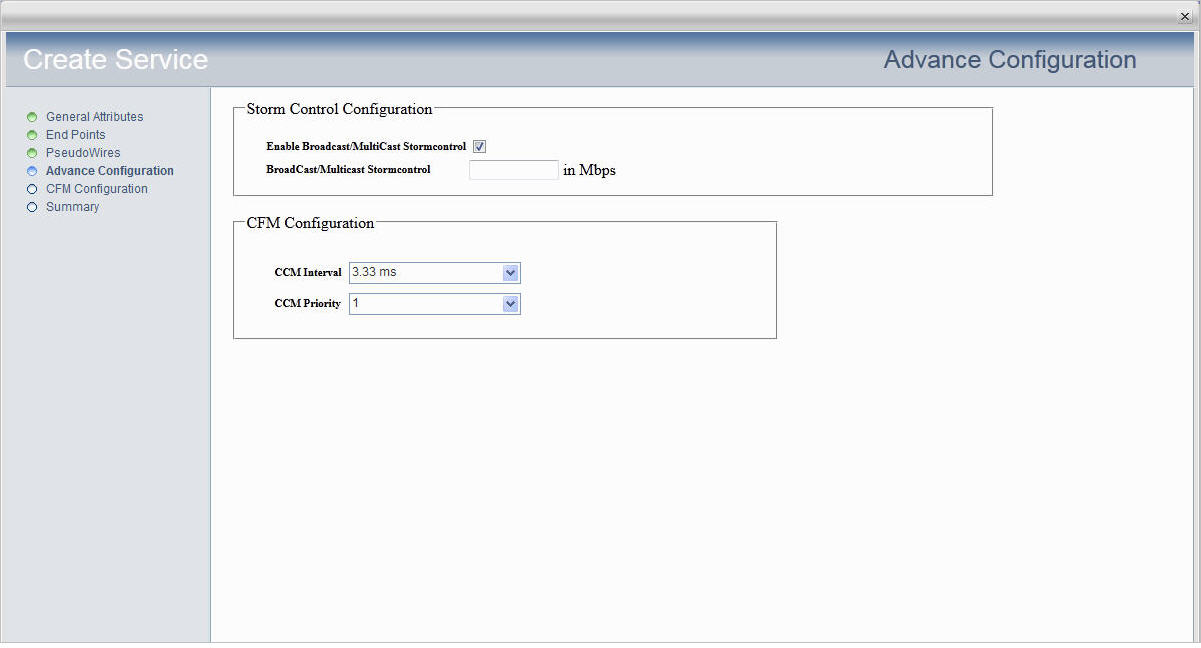
Click Next to view the summary of the service created.
Advance Configuration parameters
Parameter |
Description |
Default Value |
Acceptable Values |
|---|---|---|---|
LLF Configuration |
|||
CCM Interval |
The interval at which CCMs are sent. |
3.33ms |
|
CSF Interval |
Determines transmission periodicity of frames with Ethernet CSF information. |
10s |
|
Enable CSF |
The Ethernet client signal fail function (ETH-CSF) is used by a MEP to propagate to a peer MEP the detection of a failure or defect event in an Ethernet client signal when the client itself does not support appropriate fault or defect detection or propagation mechanisms. |
Enable |
-- |
Source Node |
Displays the source node. |
-- |
-- |
Source MEPID |
The identifier assigned to a source node MEP. |
-- |
1 to 8191 |
Destination Node |
Displays the destination node. |
-- |
-- |
Destination MEPID |
The identifier assigned to a destination node MEP. |
-- |
1 to 8191 |
MA Name |
Maintenance Association Name. |
Auto-generated by NMS |
Alphanumeric |
Primary VID |
Enter the VLAN ID for service level MEP. Primary VID value should be within the flowpoint template range attached to the service and must be different for up_mep and down_mep on the same service. |
-- |
Any one value within the service VLAN range. |
Storm Control Configuration |
|||
Enable Broadcast/MultiCast Stormcontrol |
Select the check box to enable broadcast or multicast control. |
-- |
-- |
Broadcast/MultiCast Stormcontrol |
Enter the value in Mbps. |
-- |
Depends on the node being used. |
CFM Configuration |
|||
CCM Interval |
The interval at which CCMs are sent. |
3.33ms |
|
CCM Priority |
Priority assigned to the CCM packets. |
0 |
0 to 7 |
On CFM Configuration page, the parameters to configure MEP is displayed as shown in the following figure:
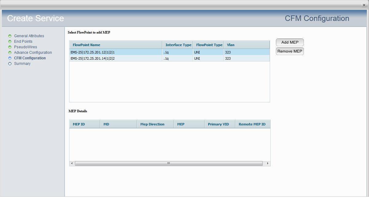
Select the end point and click Add MEP button. The MEP Creation window is displayed.
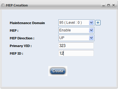
MEP Configuration parameters
Parameter |
Description |
Default Value |
Acceptable Values |
|---|---|---|---|
Maintenance Domain |
Maintenance domain is an Administrative Domain for the purpose of managing and administering a network. |
-- |
MD level: 0 to 7 and MD name with alphanumeric not exceeding 48 bytes. |
MEP |
Enable or disable MEP from the drop down menu. |
Enable |
|
MEP Direction |
Select the maintenance point direction as UP or DOWN. |
UP |
|
Primary VID |
The VLAN ID of the EVC/Service on which this MEP is created. |
-- |
Any VLAN within the VLAN-Range of the flow-point on which MEP is to be created. |
MEP ID |
The identifier assigned to a local MEP. |
-- |
1 to 8191 |
On Summary page of Create Service, the end points with the connecting link is displayed as shown in the following figure:
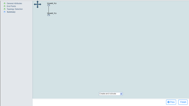
NOTE: This procedure is applicable for creating ELAN service in .1q/.1ad where more than two end points can be selected.
To create a .1q/.1ad service having EPL objects, first create an EPL object at node level. Then in NMS, at Adding End Points step, after selecting the desired port, uncheck the check box under All column and enter the VLAN value for that port. The same port having EPL object can be used for creating other service with a different VLAN value.