PseudoWire Status Messaging (PWSM) enabled on a MPLS-TP service allows fault notification on that service. This service can be created on an OAM enabled tunnel only.
Perform the following steps to create a MPLS-TP service with PWSM:
> To create an ELINE service, select the Service Type as 'ELINE'.
> To create an ELAN service, select the Service Type as 'ELAN'.
> To create the service in Non Qos Domain, select the Domain as 'Non Qos Domain'.
> To create the service in Qos Domain, select the Domain as 'Qos Domain'.
> To create the service in any of the two domain, select the Domain as 'All Domain'.
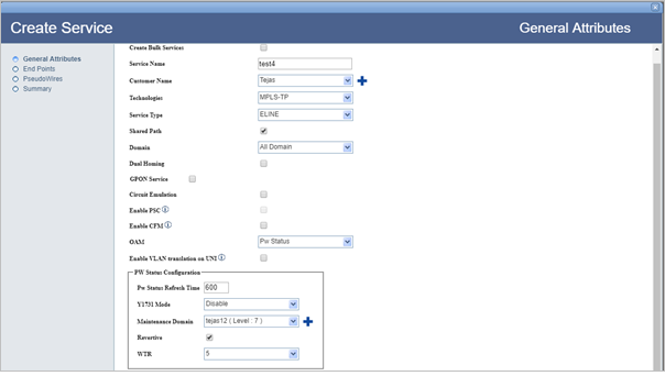
Refer General Attributes parameters table in the topic Create MPLS-TP service for description of parameters on General Attributes page.
There are two ways of searching the desired node from the list as explained follows:
> Enter the IP address/user label of the node in the text box provided and click ![]() (Search Node by IP Address or UserLabel). Or,
(Search Node by IP Address or UserLabel). Or,
> Click ![]() (Add switches using map view) and select desired node from the Topology selection window launched. Click Done. Note that only one node can be added at a time.
(Add switches using map view) and select desired node from the Topology selection window launched. Click Done. Note that only one node can be added at a time.
> If Domain is selected as 'Non Qos Domain' or All Domain' in General Attributes page, enter the VLAN value only. For All Domain the UNI port can be associated with TCProfile and CoS-0.
> If Domain is selected as 'Qos Domain', enter the VLAN value and associate a Priority Mapping Profile or DSCP Mapping Profile or a pair of TCProfile and COS values.
To view the bandwidth utilization, click View BW. View Port BW Utilization window is displayed with the bandwidth utilization details of Ingress and Egress Port.
To view the used VLAN range, click Show Used VLans. View Used VLAN Range(s) window is displayed with a list of used VLAN values for the selected port.
An ELine service must have two endpoints as shown in the following figure:
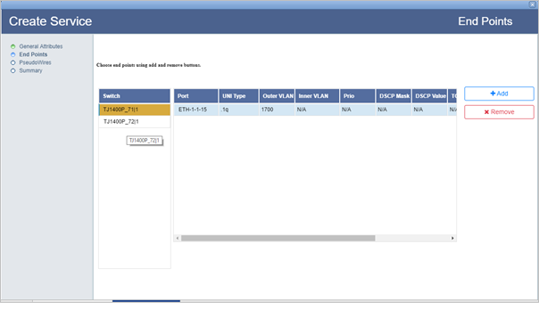
NOTE: In case of an ELAN Service Type, more than two end points can be added and for each end point, a different VLAN value for the UNI port can be applied.
Refer End Points parameters table in the topic Create MPLS-TP service for description of parameters on End Points page.
The PseudoWires page of Create Service provides the options to add or remove protection, selection of pseudowire path manually or automatic path detection, and MA configuration.
To find path for the pseudowire automatically,
Graphical representation of the pseudowire detected automatically is displayed under the View tab as shown in the following figure. Details of work and protect path, excluded switches and excluded tunnels is available under Details:
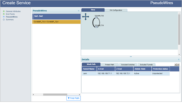
NOTE: When finding the pseudowire path automatically, the user is provided an option to exclude switches/tunnels. Select Excluded Switches and Excluded Tunnels tab. Click Add button and select the desired nodes and/links. Click Exclude Nodes or Exclude Links followed by Done. Remove button can be used to delete the added data. Select Find Path. Pseudowire path is calculated once again, excluding the selected switches/tunnels in the path.
To find path for the pseudowire manually,
(i) Direct Path Selection: This option is used for direct path selection between two end points with no intermediate nodes in between.
Select a direct path/link between the two selected end points (highlighted in black) and click Add Work. The pseudowire path is added and the link color changes from pink to blue. If the ![]() (Protection) check box was selected on the PseudoWires page, Add Protect button will get displayed. Select another path/link between the two selected end points and click Add Protect > Done.
(Protection) check box was selected on the PseudoWires page, Add Protect button will get displayed. Select another path/link between the two selected end points and click Add Protect > Done.
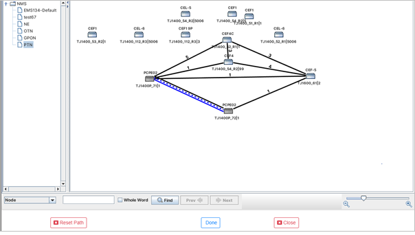
(ii) Partial Link Selection: This option is used when the user has to add more than one link to create a pseudowire path between the two end points.
Select the Partial Link Selection check box. Select the path/link connecting the two selected end points and click Add Links. The path/link gets highlighted in cyan color. Click Add Work. The pseudowire path is added and the link color changes from cyan to blue. To add protection, select another path/link connecting the two selected end points and click Add Links > Add Protect > Done. In case path addition fails, the partial link selection will be reset.
The PW Status Info page of Create Service provides the option to select attachment circuits for the pseudowire end points.
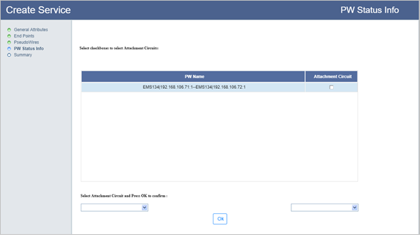
For ELAN service, repeat the two steps a and b above for adding attachment circuit to other pseudowire end points. In case if the user desires to change the added attachment circuit on a pseudowire, select that pseudowire under PW Name. The added attachment circuit will be displayed under the end points. Select another attachment circuit from the drop down menu and click OK.
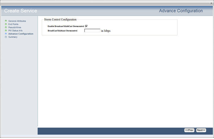
The Advance Configuration window is displayed when the Service Type is selected as 'ELAN'. Select the Enable Broadcast/MultiCast Stormcontrol check box if desired and then enter the BroadCast/Multicast Stormcontrol value in Mbps in the text box displayed. Click Next to view the summary of the service.
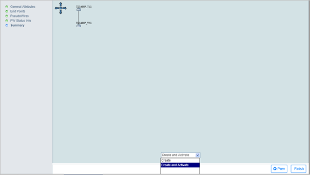
On Summary page of Create Service, the end points with the connecting pseudowire is displayed.
Following figure shows the summary of the ELINE service type:
