TJ5500 supports singleton services using .1q/.1ad.
Perform the following steps to create new singleton service:
A series of new windows will now be displayed for step-by-step creation of a service.
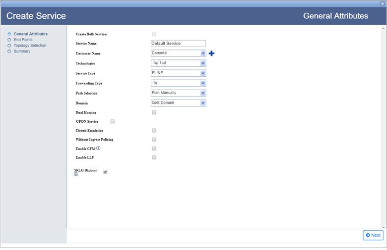
General Attributes parameters
Parameter |
Description |
Default Value |
Acceptable Values |
|---|---|---|---|
Service Name |
Enter a name for the service. Service name should begin with an alphabet. |
Default Service |
|
Customer Name |
Select the name of the customer from the options available in drop down list; or to create a new customer, click |
custName |
|
Technologies |
Select the type technology for service creation. |
.1q/.1ad |
-- |
Service Type |
Select the type of service to be created. |
ELINE |
NOTE: Only ELINE service is supported for singleton services. |
Domain |
Select the domain for the service being created. Click Add on End Points page to choose the end point and the UNI port for the service. |
Qos Domain |
NOTE: Only Qos Domain is supported for singleton services. |
Dual Homing |
Dual homing is not supported for singleton service. |
-- |
-- |
Circuit Emulation |
Select the check box to configure a CEM service. NOTE: On selecting Circuit Emulation check box, Configure CESIWF is added to steps of service creation on left panel of the General Attributes window. |
-- |
-- |
Capacity |
Select the capacity from the drop down menu. |
E1/DS1 |
|
CESIWF Count |
Enter the value for the number of CESIWFs to be created. |
1 |
Number of CESIWFs to be created. |
Enable CFM |
The parameter is used to enable Connectivity Fault Management (CFM). NOTE: This parameter is not supported for singleton service. |
-- |
-- |
Enable LLF |
This parameter is not supported for singleton service. |
-- |
-- |
SRLG Disjoint |
Select the check box to ensure that the work and protect paths selected are mutually link SRLG disjoint. The check box will be selected by default. NOTE: Un-check the parameter as it is not supported for singleton service. |
-- |
-- |
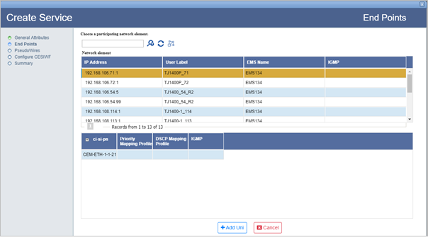
There are two ways of searching the desired node from the list explained as follows:
> Enter the IP address/user label of the node in the text box provided and click ![]() (Search Node by IP Address or UserLabel). Or,
(Search Node by IP Address or UserLabel). Or,
> Click ![]() (Add switches using map view) and select desired NEs from the Topology selection window launched. Click Done. Note that only one node can be added at a time.
(Add switches using map view) and select desired NEs from the Topology selection window launched. Click Done. Note that only one node can be added at a time.
To view the bandwidth utilization, click View BW. View Port BW Utilization window is displayed with the bandwidth utilization details of Ingress and Egress Port.
To view the used VLAN range, click Show Used VLans. View Used VLAN Range(s) window is displayed with a list of used VLAN values for the selected port.
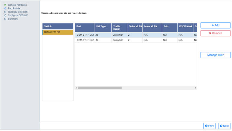
An ELine service must have two end points as shown in the following figure:
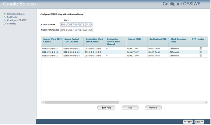
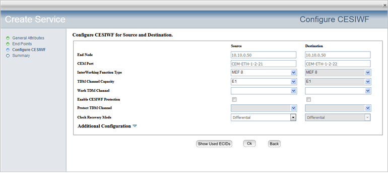
(i) Click Show Used ECIDs. View Used ECID page is displayed showing the used [existing and/or planned] ECID(s) and TDM Channel(s), if any.
Select the required Network Element and the corresponding Switch followed by the Port.
(iii) Do one of the following:
> To view used ECIDs, select the action as Show used ECIDs from the drop down menu. The used ECID values for the selected port is displayed under the right column.
> To filter TDM channel, select the action as Filter TDM Channel from drop down menu and enter the port number in TDM Channel text box in ci-si-pn format. Click Go. A message will be displayed whether that TDM channel is free for use or not.
> To filtr ECID, select the action as Filter ECID from drop down menu and enter the ECID number in ECID Value text box. ECID must be a number in range 1 - 1048575. Click Go. A message will be displayed whether the ECID is free for use or not.
(iv) Click Close to exit this window.
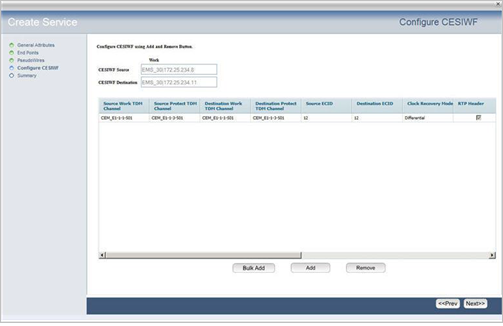
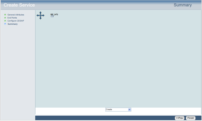
On Summary page of Create Service, the end point is displayed as shown in the following figure:
