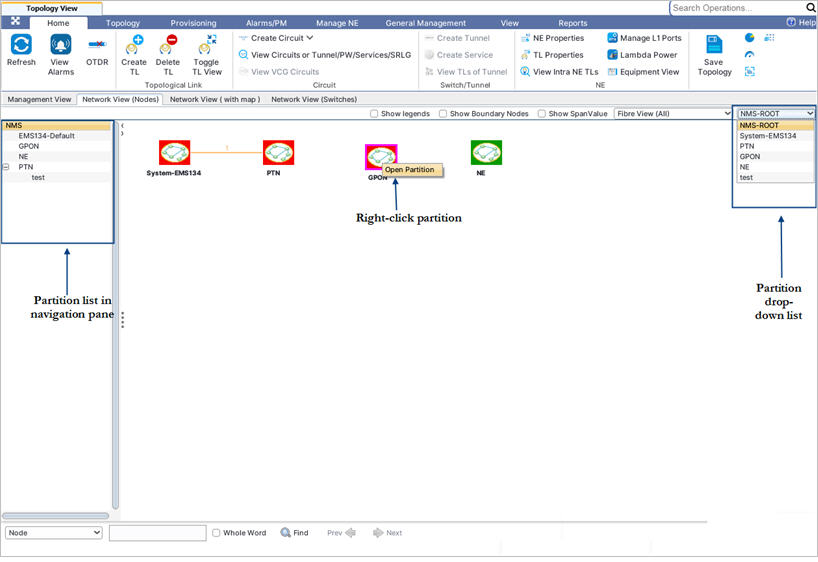
Go to Topology menu and click Topology View option. On Topology View window, click Network View (Nodes) tab.
The Network View (Nodes) tab displays a list of all partitions present under NMS root under left hand navigation pane and a graphical representation in the work area.
Under NMS root, do one of the following to view the nodes under a partition:

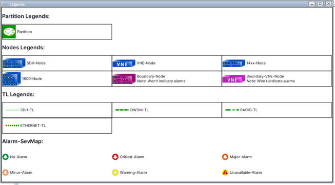
To View Legends select Show legends check box. Legends window is displayed as shown in the following figure:

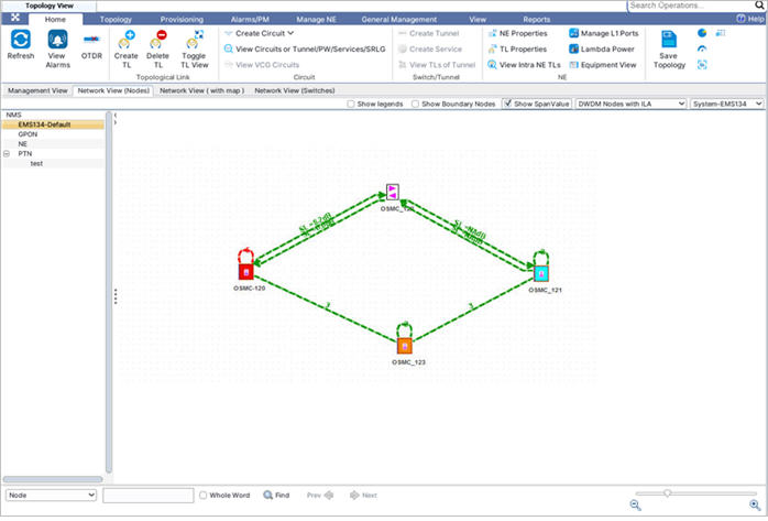
To view Span Value, perform the following steps to view the span loss value on amplifier TLs:
If the user desires to view the label of a single TL, expand the link between two nodes by using Toggle TL View button and select the desired TL.

To view boundary nodes
NOTE: Verify that inter-EMS Topological links are present in NMS. If not, create few inter-EMS topological links by moving the nodes to another EMS i.e. the adjacent nodes are present in another EMS.
Boundary nodes are the nodes that are part of the inter-EMS topological links and are present in the other EMS. For example, consider two EMS(s), EMS-1 and EMS-2. Node A is added in EMS-1 and nodes B and C are added in EMS-2. Nodes A, B and C are in ring such that the topological link between A and B and between A and C are inter-EMS topological links. In the Topology View of EMS-1 partition, verify that the nodes B and C are represented in dark pink color. Verify that the inter-EMS topological link between A and B and nodes A and C are displayed in EMS-1 partition. Verify that the topological link between nodes B and C is not displayed in EMS-1 partition.
To display the boundary nodes in the topology view, do the following steps:
Fibre View
On Network View (Nodes) tab, you can select from the following views provided in the drop-down menu:
NOTE: OSC View For DWDM Nodes option is not supported in this product release.