Previous Topic

Next Topic

Book Contents

Create Topological Link

Different type of Topological Links that can be created from Topology View > Network View (Nodes) window are:

Perform the following steps to create a SDH/SONET or Ethernet topological link:

  1. Go to Topology menu and click Topology View option. Topology View window is displayed.
  2. Click Network View (Nodes) tab and select the desired partition from the left hand navigation pane.
  3. Select the two desired nodes by using CTRL button (nodes get highlighted in pink upon selection).

    The node you select first becomes the Source Node and the second becomes the Destination Node.
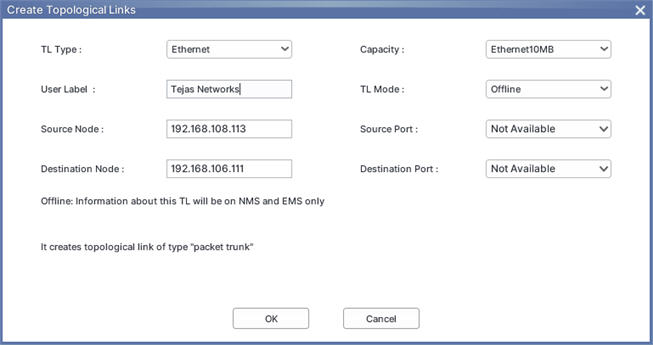
  4. Click (Create Topological Link). Create Topological Links window is displayed.

    Create Topological Links window

  5. Select TL Type as SDH/SONET or Ethernet and its Capacity as desired from the drop-down list.
  6. Select the Source Port and the Destination Port on the source and destination nodes respectively from the drop-down list. Enter the values in remaining fields as desired. For more information, refer Create Topological Links parameters table.
  7. Click OK. TopoLogical Link Creation Request Sent message is displayed.
  8. Click OK.

    An Ethernet TL is represented as dashed green line whereas a SDH TL as solid green line.

Create Topological Links parameters

Field

Description

TL Type

Select the TL Type as desired from the drop-down list. The options available are:

  • SDH/SONET
  • RADIO
  • OTN
  • OTN-DWDM
  • Ethernet
  • DWDM
  • Amplifier

User Label

Enter the value to be used to identify the topological link. By default, the value is 'Tejas Networks'.

Source Node

Displays the IP address of the selected local or source node.

Destination Node

Displays the IP address of the selected remote or destination node.

Capacity

Displays the capacities supported on the corresponding TL Type. Select the desired capacity for the TL type selected.

TL Mode

Select the TL mode from the options listed as follows:

  • Offline: means the information about the TL being created will be on NMS and EMS only.
  • Online: means the information about the TL being created will be on NMS, EMS, and node.
  • Manual: means these are logical TLs for representation purpose only and information will be present only in NMS and EMS. This mode is supported only for TL creation between TJ1400P-M switches and other Tejas nodes.

Source Port

Select the source port on the node from the drop-down list.

Destination Port

Select the destination port on the node from the drop-down list.

NOTE: Additional details are provided about the selected TL Type and TL Mode on Create Topological Links window.

See also

Topology View

Understand Network View (Nodes) tab

Understand Network View (Switches) tab

Open parent partition

Delete Topological Links

Toggle TL view

Create circuits from Topology View menu

View circuits or Tunnels/Pseudowire/Services/SRLG

Set Span Loss parameters

Span Loss report generation

Assign SRLG ID to TLs from Topology View

Create VPLS Cloud link

Create Open ERP over VPLS Cloud

Generate bandwidth utilization report of packet trunks

Enable and disable PM

View alarms at Partition/Node/Topological link level

View alarms on Amplifiers

View bandwidth utilization on Topology View

Node Augmentation

Augment Node_Ethernet

Remove node from Topology

Re-Augment a node

Create new Third Party Cloud

Management view of EMS

Node administration view of EMS

NE software upgrade

Save Topology

Resync EMS

View optical power reports of selected node(s) or TL(s)

Live monitoring of optical power, Lambda power, and Performance

Monitor alarms

Upload background image

Launch node page

View Historical alarms

View PM details

View EMS level report

Create services from Topology View menu

Create Tunnel from Topology View menu