![]()
![]()
![]()
![]()
|
|
|
|
|
The Configuration submenu in the System menu contains links to pages that allow you to configure device parameters. The configuration folder contains links to the following features:
After a successful login, the System Description page displays. Use this page to configure and view general device information. To display the System Description page, click System > Configuration > System Description in the navigation menu.
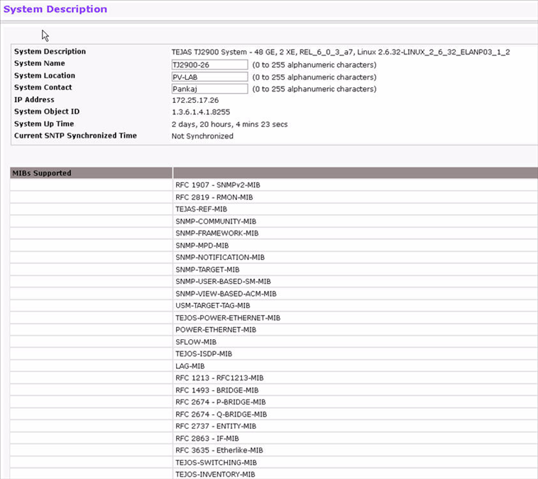
System Description Fields
Field |
Description |
|---|---|
System Description |
The product name of this switch. |
System Name |
Enter the name you want to use to identify this switch. You may use up to 31 alpha‐numeric characters. The factory default is blank. |
System Location |
Enter the location of this switch. You may use up to 31 alpha‐numeric characters. The factory default is blank. |
System Contact |
Enter the contact person for this switch. You may use up to 31 alpha‐numeric characters. The factory default is blank. |
IP Address |
The IP Address assigned to the network interface. To change the IP address. |
System Object ID |
The base object ID for the switch's enterprise MIB. |
System Up Time |
Displays the number of days, hours, and minutes since the last system restart. |
Current SNTP Synchronized Time |
Displays the current SNTP synchronized time. |
MIBs Supported |
Displays the list of MIBs supported by the management agent running on this switch. |
Defining System Information
The system parameters are applied, and the device is updated.
NOTE: If you want the switch to retain the new values across a power cycle, you must perform a save task.
IEEE 802.3x flow control works by pausing a port when the port becomes oversubscribed and dropping all traffic for small bursts of time during the congestion condition. This can lead to high‐priority and/or network control traffic loss. When 802.3x flow control is enabled, lower speed switches can communicate with higher speed switches by requesting that the higher speed switch refrains from sending packets. Transmissions are temporarily halted to prevent buffer overflows. To display the Switch Configuration page, click System > Configuration > Switch in the navigation menu.
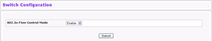
Switch Configuration Fields
Field |
Description |
|---|---|
IEEE 802.3x Flow Control Mode |
Enables or disables IEEE 802.3x flow control on the system. The factory default is disabled. |
Enable |
Enables flow control so that the switch can communicate with higher speed switches. |
Disable |
Disables flow control so that the switch does not send pause packets if the port buffers become full. |
If you change the mode, click Submit to apply the changes to the system. If you want the switch to retain the new values across a power cycle, you must perform a save.
Use the IP Address Conflict Detection page to run the IP Address Conflict Detection tool, which detects IP address conflicts for IPv4 addresses. When a conflict is detected, the switch updates the status on the page, generates an SNMP trap, and a logs a message noting the conflict. To display the IP Address Conflict Detection page, click System > Configuration > IP Address Conflict Detection in the navigation menu.
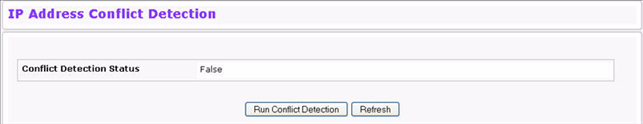
IP Address Conflict Detection Fields
Field |
Description |
|---|---|
Conflict Detection Status |
Shows whether an address conflict has been detected since status was last reset. |
Run Conflict Detection |
This task runs the conflict detection process. |
Last Conflicting IP Address |
The IP address of the interface that was last found to be conflicting. This field displays only if a conflict has been detected since the switch was last reset. |
Last Conflicting MAC Address |
The MAC address of the remote host associated with the IP address that was last found to be conflicting. This field displays only if a conflict has been detected since the switch was last reset. |
Time Since Conflict Detected |
The time elapsed (displayed in days, hours, mins, secs) since the last conflict was detected (provided a reset did not occur in the meantime). This field displays only if a conflict has been detected since the switch was last reset. |
To run the tool and check for possible address conflicts, click Run Conflict Detection. If the conflict detection status is true, click Reset Conflict Detection Status to clear the information and run the tool again.
Some platforms have a built‐in service port that can serve as a dedicated network management interface. For systems that have the service port, the Service Port Configuration page allows you to configure network information for the switch. To access the Service Port Configuration page, click System > Configuration > Service Port in the navigation menu.
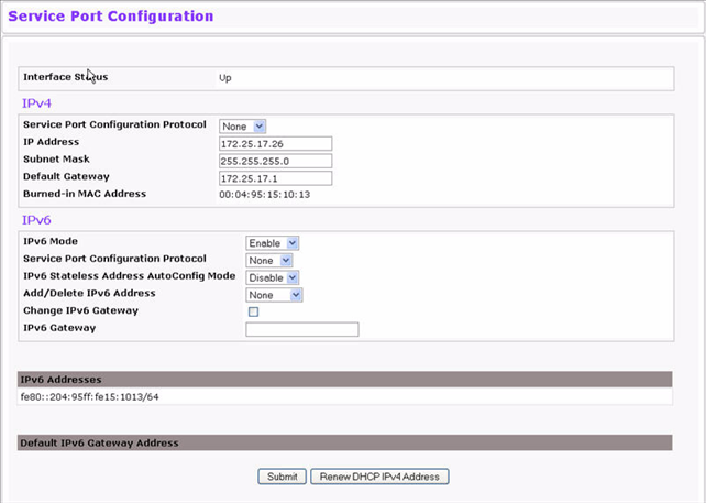
Service Port Configuration Fields
Field |
Description |
|---|---|
IPv4 Fields: These display IPv4 configuration information. |
|
Service Port Configuration Protocol |
Specify what the switch should do following power‐up. The factory default is one. The options are as follows:
|
IP Address |
The IP address of the network interface. The factory default value is 0.0.0.0. NOTE: Each part of the IP address must start with a number other than zero. |
Subnet Mask |
The IP subnet mask for the interface. The factory default value is 0.0.0.0. |
Default Gateway |
The default gateway for the IP interface. The factory default value is 0.0.0.0. |
Burned‐in MAC Address |
This read‐only field displays the MAC address that is burned‐in to the network card at the factory. This MAC address is used for in‐band connectivity if you choose not to configure a locally administered address. |
IPv6 Fields: If the system supports IPv6, these fields display IPv6 configuration information. |
|
IPv6 Mode |
Enables or disables IPv6 mode on the interface. |
Service Port Configuration Protocol |
Specify what the switch should do following power‐up. The factory default is None. The options are as follows:
|
IPv6 Stateless Address AutoConfig Mode |
Enables or Disables the IPv6 stateless address autoconfiguration on the management port. The factory default is None Enables or Disables the IPv6 stateless address autoconfiguration on the management port. The factory default is None. |
Change IPv6 Gateway |
Select the check box to configure an IPv6 Address. |
IPv6 Gateway |
Enter the IPv6 gateway address (do not include a prefix). |
Add/Delete IPv6 Address |
Select to Add or Remove IPv6 Addresses. The fields New IPv6 Address and EUI Flag are visible when we select the Add from this menu. |
New IPv6 Address |
Displays when Add IPv6 Address is selected. Adds IPv6 address. |
EUI Flag |
Displays when Add IPv6 Address is selected. Sets the EUI flag while configuring a new IPv6 address when TRUE is selected. The Default is FALSE. |
IPv6 Addresses |
Displays IPv6 addresses. |
Default IPv6 Gateway Address |
Displays the address(es) entered in the IPv6 Gateway field. |
To renew the IPv4 address learned from a DHCP server on the service port, click Renew DHCP IPv4 Address. If you change any of the parameters on this page, click Submit to apply the changes to the system. If you want the switch to retain the new values across a power cycle, you must perform a save.
When IPv6 is enabled on the service port, and a ping is initiated to a neighbor, the neighbor is added to the cache (if successful). This page displays data on these ports.
To display the page, click System > Configuration > Service Port NDP Summary.
Service Port NDP Summary Fields
Field |
Description |
|---|---|
IPv6 Address |
Displays the IP address of the neighbor. |
MAC Address |
Displays the MAC address of the neighbor. |
isRtr |
Indicates whether the neighbor is a router. If the neighbor is a router, the value is TRUE. If the neighbor is not a router, the value is FALSE. |
Neighbor State |
Specifies the state of the neighbor cache entry. Following are the states for dynamic entries in the IPv6 neighbor discovery cache:
|
Last Updated |
Displays the time since the address was confirmed to be reachable. |
The Service Port DHCPv6 Client Statistics page displays DHCPv6 client statistics.
To display the Service Port DHCP Client Statistics page, click System > Configuration > Service Port DHCPv6 Client Statistics.
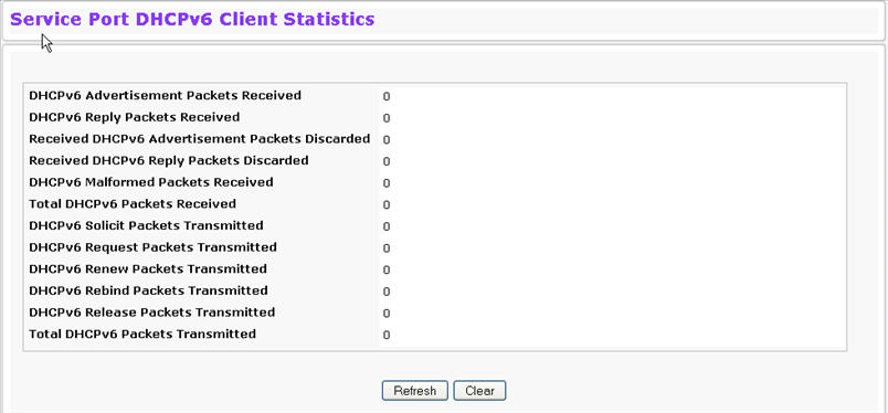
Service Port DHCPv6 Client Statistics Fields
Field |
Description |
|---|---|
DHCPv6 Advertisement Packets Received |
Number of DHCPv6 Advertisement packets received on the service port. |
DHCPv6 Reply Packets Received |
Number of DHCPv6 Reply packets received on the service port. |
Received DHCPv6 Advertisement Packets Discarded |
Number of DHCPv6 Advertisement packets discarded on the service port. |
Received DHCPv6 Reply Packets Discarded |
Number of DHCPv6 Reply packets discarded on the service port. |
DHCPv6 Malformed Packets Received |
Number of DHCPv6 packets that are received malformed on the service port. |
Total DHCPv6 Packets Received |
Total number of DHCPv6 packets received on the service port. |
DHCPv6 Solicit Packets Transmitted |
Number of DHCPv6 Solicit packets transmitted on the service port. |
DHCPv6 Request Packets Transmitted |
Number of DHCPv6 Request packets transmitted on the service port. |
DHCPv6 Renew Packets Transmitted |
Number of DHCPv6 Renew packets transmitted on the service port. |
DHCPv6 Rebind Packets Transmitted |
Number of DHCPv6 Rebind packets transmitted on the service port. |
DHCPv6 Release Packets Transmitted |
Number of DHCPv6 Release packets transmitted on the service port. |
Total DHCPv6 Packets Transmitted |
Total number of DHCPv6 packets transmitted on the service port. |
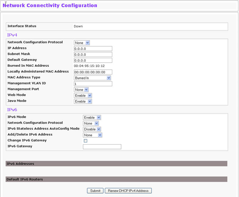
The network interface is the logical interface used for in‐band connectivity with the switch through any of the switch's front panel ports. The configuration parameters associated with the switch's network interface do not affect the configuration of the front panel ports through which traffic is switched or routed.
The Network Connectivity Configuration page allows you to change the IPv4 and IPv6 information using the Web interface. To access the page, click System > Configuration > Network Connectivity in the navigation menu.
Network Connectivity Configuration Fields
Field |
Description |
|---|---|
IPv4 Fields |
|
Network Configuration Protocol |
Specify what the switch should do following power-up. The factory default is None. The options are as follows:
|
IP Address |
The IP address of the network interface. The factory default value is 0.0.0.0. NOTE: Each part of the IP address must start with a number other than zero. |
Subnet Mask |
The IP subnet mask for the interface. The factory default value is 0.0.0.0. |
Default Gateway |
The default gateway for the IP interface. The factory default value is 0.0.0.0. |
Burned-in MAC Address |
This read-only field displays the MAC address that is burned-in to the network card at the factory. This MAC address is used for in-band connectivity if you choose not to configure a locally administered address. |
Locally Administered MAC Address |
Specifies a locally administered MAC address for in-band connectivity instead of using the burned-in universally administered MAC address. In addition to entering an address in this field, you must also set the MAC address type to locally administered. Enter the address as twelve hexadecimal digits (6 bytes) with a colon between each byte. Bit 1 of byte 0 must be set to a 1 and bit 0 to a 0. The byte 0 must have a value between x'40' and x'7F'. |
MAC Address Type |
Specify whether the burned-in or the locally administered MAC address should be used for in-band connectivity. The factory default is to use the burned-in MAC address. |
Management VLAN ID |
Specify the management VLAN ID of the switch. It may be configured to any value in the range of (1 to 4093). The management VLAN is used for management of the switch. This field is configurable for administrative users and read-only for other users. |
Web Mode |
Enables/Disables Web Mode on the switch. |
Java Mode |
Enables/Disables Java mode on the switch. |
If you change any of the network connectivity parameters, click Submit to apply the changes to the system. If you want the switch to retain the new values across a power cycle, you must perform a save. Click Renew DHCP IPv4 Address to force the interface to release the current DHCP-assigned information and submit a request for new information.
When IPv6 is enabled on the service port, and a ping is initiated to a neighbor, the neighbor is added to the cache (if successful). This page displays data on these ports. To access this page, click System > Configuration > Network Connection NDP Summary.
Network Connection NDP Summary
Field |
Description |
|---|---|
IPv6 Address |
Displays the IP address of the neighbor. |
MAC Address |
Displays the MAC address of the neighbor. |
isRtr |
Indicates whether the neighbor is a router. If the neighbor is a router, the value is TRUE. If the neighbor is not a router, the value is FALSE. |
Neighbor State |
Specifies the state of the neighbor cache entry. Following are the states for dynamic entries in the IPv6 neighbor discovery cache:
|
Last Updated |
Displays the time since the address was confirmed to be reachable. |
The Network Port DHCPv6 Client Statistics page displays DHCPv6 client statistics.
To display the Network Port DHCP Client Statistics page, click System > Configuration > Network Port DHCPv6 Client Statistics.
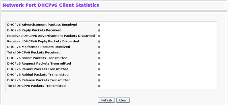
Network Port DHCPv6 Client Statistics Fields
Field |
Description |
|---|---|
DHCPv6 Advertisement Packets Received |
Displays the number of DHCPv6 Advertisement packets received on the network port. |
DHCPv6 Reply Packets Received |
Displays the number of DHCPv6 Reply packets received on the network port. |
Received DHCPv6 Advertisement Packets Discarded |
Displays the number of DHCPv6 Advertisement packets discarded on the network port. |
Received DHCPv6 Reply Packets Discarded |
Displays the number of DHCPv6 Reply packets discarded on the network port. |
DHCPv6 Malformed Packets Received |
Displays the Number of DHCPv6 packets that are received malformed on the network port. |
Total DHCPv6 Packets Received |
Displays the total number of DHCPv6 packets received on the network port. |
DHCPv6 Solicit Packets Transmitted |
Displays the number of DHCPv6 Solicit packets transmitted on the network port. |
DHCPv6 Request Packets Transmitted |
Displays the number of DHCPv6 Request packets transmitted on the network port. |
DHCPv6 Renew Packets Transmitted |
Displays the number of DHCPv6 Renew packets transmitted on the network port. |
DHCPv6 Rebind Packets Transmitted |
Displays the number of DHCPv6 Rebind packets transmitted on the network port. |
DHCPv6 Release Packets Transmitted |
Displays the number of DHCPv6 Release packets transmitted on the network port. |
Total DHCPv6 Packets Transmitted |
Displays the total number of DHCPv6 packets transmitted on the network port. |
Use the DHCP Client Options page to configure DHCP client settings on the system. To access the DHCP Client Options page, click System > Configuration > DHCP Client Options in the navigation menu.
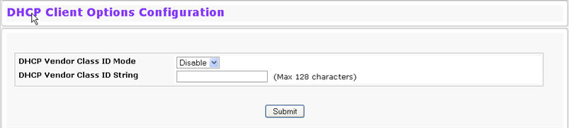
DHCP Client Options
Field |
Description |
|---|---|
DHCP Vendor Class ID Mode |
Enables/Disables the vendor class identifier mode. |
DHCP Vendor Class ID String |
The string added to DHCP requests as Option-60. (Vendor Class Identifier option). |
Use the HTTP Configuration page to configure the HTTP server settings on the system. To access the HTTP Configuration page, click System > Configuration > HTTP Configuration in the navigation menu.
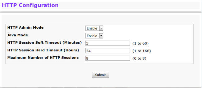
HTTP Configuration Fields
Field |
Description |
|---|---|
HTTP Admin Mode |
This select field is used to Enable or Disable the Administrative Mode of HTTP. The currently configured value is shown when the web page is displayed. The default value is Enable. If you disable the HTTP admin mode, access to the web interface is limited to secure HTTP, which is disabled by default. |
Java Mode |
This select field is used to Enable or Disable the web Java Mode. This applies to both secure and un-secure HTTP connections. The currently configured value is shown when the web page is displayed. The default value is Enable. |
HTTP Session Soft Timeout |
This field is used to set the inactivity timeout for HTTP sessions. The value must be in the range of (1 to 60) minutes. A value of zero corresponds to an infinite timeout. The default value is 5 minutes. The currently configured value is shown when the web page is displayed. |
HTTP Session Hard Timeout |
This field is used to set the hard timeout for HTTP sessions. This timeout is unaffected by the activity level of the session. The value must be in the range of (1 to 168) hours. A value of zero corresponds to an infinite timeout. The default value is 24 hours. The currently configured value is shown when the web page is displayed. |
Maximum Number of HTTP Sessions |
This field is used to set the maximum allowable number of HTTP sessions. The value must be in the range of (0 to 8). The default value is 8. The currently configured value is shown when the web page is displayed. |
Telnet is a terminal emulation TCP/IP protocol. ASCII terminals can be virtually connected to the local device through a TCP/IP protocol network. Telnet is an alternative to a local login terminal where a remote login is required.
The switch supports up to five simultaneous telnet sessions. All CLI commands can be used over a telnet session. The Telnet Session Configuration page allows you to control inbound telnet settings on the switch. Inbound telnet sessions originate on a remote system and allow a user on that system to connect to the switch CLI.
To display the Telnet Session Configuration page, click System > Configuration > Telnet Session in the navigation menu.
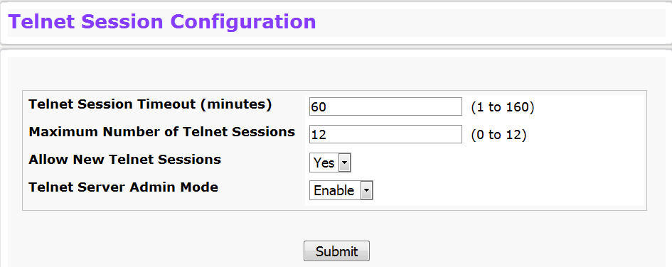
Telnet Session Configuration Fields
Field |
Description |
|---|---|
Telnet Session Timeout (minutes) |
Specify how many minutes of inactivity should occur on a telnet session before the session is logged off. You may enter any number from 1 to 160. The factory default is 5. NOTE: When you change the timeout value, the new value is applied to all active and inactive sessions immediately. Any sessions that have been idle longer than the new timeout value are disconnected immediately. |
Maximum Number of Telnet Sessions |
From the drop-down menu, select how many simultaneous telnet sessions to allow. The maximum is 12, which is also the factory default. A value of 0 indicates that no outbound Telnet session can be established. |
Allow New Telnet Sessions |
Controls whether to allow new telnet sessions:
|
Telnet Server Admin Mode |
Administrative mode for inbound telnet sessions. Setting this value to disable shuts down the telnet port. If the admin mode is set to disable, then all existing telnet connections are disconnected. The default value is Enable. |
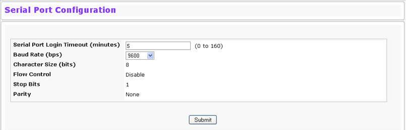
The Serial Port Configuration page allows you to change the switch’s serial port settings. In order for a terminal or terminal emulator to communicate with the switch, the serial port settings on both devices must be the same. Some settings on the switch cannot be changed.
To view or configure the serial port settings on the switch, click System > Configuration > Serial Port Configuration in the navigation menu.
Serial Port Fields
Field |
Description |
|---|---|
Serial Port Login Timeout (minutes) |
Indicates how many minutes of inactivity should occur on a serial port connection before the switch closes the connection. Enter a number between 0 and 160. The factory default is 5. Entering 0 disables the timeout. |
Baud Rate (bps) |
Select the default baud rate for the serial port connection from the menu. The factory default is 115200 baud for Linux® platforms and 9600 baud for VxWorks® platforms. |
Character Size (bits) |
The number of bits in a character. This is always 8. |
Flow Control |
Whether hardware flow control is enabled or disabled. It is always disabled. |
Stop Bits |
The number of stop bits per character. Its is always 1. |
Parity |
The parity method used on the serial port. It is always None. |
If you change any data, click Submit to apply the changes to the system. If you want the switch to retain the new values across a power cycle, you must perform a save.
By default, the switch contains two user accounts:
Both of these accounts have blank passwords by default. The names are not case sensitive.
If you log on to the switch with the user account that Read/Write privileges, you can use the User Accounts page to assign passwords and set security parameters for the default accounts. You can also add up to five read‐only accounts. You can delete all accounts except for the Read/Write account.
NOTE: Only a user with Read/Write privileges may alter data on this screen, and only one account can exist with Read/Write privileges.
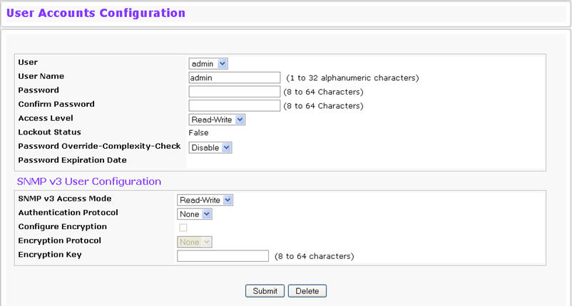
To access the User Accounts page, click System > Configuration > User Accounts in the navigation menu.
User Accounts Fields
Field |
Description |
|---|---|
User |
From the User menu, select an existing user to configure, or select Create to create a new user account. The system can have a maximum of five 'Read Only' accounts and one Read/Write account. |
User Name |
Enter the name you want to give to the new account. (You can only enter data in this field when you are creating a new account.) User names are up to 32 alphanumeric characters in length and are not case sensitive. Valid characters include all the alphanumeric characters and the dash ('-') and underscore ('_') characters. User name default is not valid. NOTE: You can change the Read/Write user name from "admin" to something else, but when you click Submit, you must re‐authenticate with the new username. |
Password |
Enter the optional new or changed password for the account. It will not display as it is typed, only asterisks (*) or dots(.) will show based on the browser used. Passwords must be greater than eight characters and can be up to 64 characters in length, and are case sensitive. |
Confirm Password |
Enter the password again, to confirm that you entered it correctly. This field will not display, but will show asterisks (*). |
Access Level |
Indicates the user's access level. The admin account always has Read/Write access, and all other accounts have Read Only access. A user with Read/Write access can also set a user’s access level to Suspend, which prevents the user from accessing the switch. |
Lockout Status |
Indicates whether the user is currently locked out. A user is locked out after a configurable number of failed login attempts. If the user is locked out, the status is True. |
Password Override- Complexity- Check |
When set to enable, the password strength checking is not in effect for this user. |
Password Expiration Date |
Indicates the date when this user’s current password will expire. This is determined by the date the password was created and the number of days specified in the aging Password Aging setting on the Password Management page. |
SNMP v3 User Configuration |
|
SNMP v3 Access Mode |
Shows the SNMPv3 access privileges for the user account. The admin account always has 'Read/Write' access, and all other accounts have 'Read Only' access. |
Authentication Protocol |
Specify the SNMPv3 Authentication Protocol setting for the selected user account. The valid Authentication Protocols are None, MD5 or SHA. If you select None, the user will be unable to access the SNMP data from an SNMP browser. If you select MD5 or SHA, the user login password will be used as the SNMPv3 authentication password, and you must specify a valid password. |
Configure Encryption |
Select the check box to change the Encryption Protocol and Encryption Key. |
Encryption Protocol |
Specify the SNMPv3 Encryption Protocol setting for the selected user account. The valid Encryption Protocols are None or DES. If you select the DES Protocol you must enter a key in the Encryption Key field. If None is specified for the Protocol, the Encryption Key field is not active for input. |
Encryption Key |
If you selected DES in the Encryption Protocol field enter the SNMPv3 Encryption Key here. Otherwise this field is not active. Key should be 8 characters in length. |
Use the following procedures to add a user account. The system supports one Read/Write user and five Read Only users.
If you want the switch to retain the new values across a power cycle, you must perform a save.
You cannot add or delete the Read/Write user, but you can change the username and password. To change the password for an existing account or to overwrite the username on an existing account, use the following procedures.
Use the following procedures to delete any of the Read Only user accounts.
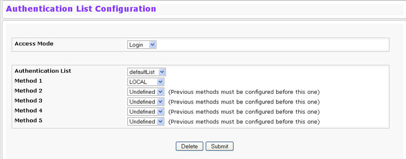
Use the Authentication List Configuration page to configure login lists. A login list specifies one or more authentication methods to validate switch or port access for the users associated with the list.
NOTE: The preconfigured users, admin and guest, are assigned to a pre-configured list named default List, which you cannot delete. All newly created users are also assigned to the defaultList until you specifically assign them to a different list.
To access the Authentication List Configuration page, click System > Configuration > Authentication List Configuration in the navigation menu.
Authentication List Configuration Fields
Field |
Description |
|---|---|
Access Mode |
A Login or Enable list specifies the authentication method you want used to validate switch or port access for the users associated with the list. The pre-configured users (admin and guest) are assigned to a pre-configured list named defaultList, which you may not delete. All newly created users are also assigned to the defaultList until you assign them to a different list. |
Authentication List |
The menu allows you to create a new authentication list or to select an existing list to view or configure. |
Method 1 |
Use the menu to select the method that should appear first in the selected authentication login list. User authentication occurs in the order the methods are selected. Possible methods are as follows:
|
Method 2 |
Use the menu to select the method, if any, that should appear second in the selected authentication login list. This is the method that will be used if the first method times out. |
Method 3 |
Use the menu to select the method, if any, that should appear third in the selected authentication login list. This is the method that will be used if the second method times out. |
Method 4 |
Use the menu to select the method, if any, that should appear fourth in the selected authentication login list. This is the method that will be used if the third method times out. |
Method 5 |
Use the menu to select the method, if any, that should appear fifth in the selected authentication login list. This is the method that will be used if the fourth method times out. |
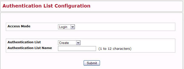
When Create is selected from Authentication List, the Create Authentication List Configuration page displays.
Create Authentication List Configuration Fields
Field |
Description |
|---|---|
Access Mode |
A Login or Enable list specifies the authentication method you want used to validate switch or port access for the users associated with the list. The pre-configured users (admin and guest) are assigned to a pre-configured list named defaultList, which you may not delete. All newly created users are also assigned to the defaultList until you assign them to a different list. |
Authentication List |
The menu allows you to create a new authentication list or to select an existing list to view or configure. |
Authentication List Name |
If you are creating a new list, enter the name you want to assign. It can be up to 15 alphanumeric characters long and is not case sensitive. |
To create a new authentication list, use the following procedures.
To modify an authentication list, use the following procedures.
Use the following procedures to remove an authentication login list from the configuration.
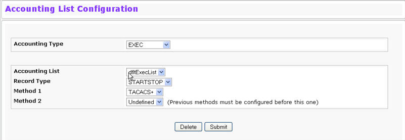
Use the Accounting List Configuration page to configure accounting list.
To access the Authentication List Configuration page, click System > Configuration > Accounting List Configuration in the navigation menu.
Accounting List Configuration Fields
Field |
Description |
|---|---|
Accounting Type |
Select Exec to account for login and logout times of a user session. Select Commands to account for user executed commands. |
Accounting List |
Select the accounting list to configure:
|
Record Type |
Specify when to send accounting messages:
|
Method 1 |
Use the menu to select the method that should appear first in the selected accounting list. User accounting occurs in the order the methods are selected. Possible methods are as follows:
|
Method 2 |
Use the menu to select the method, if any, that should appear second in the selected accounting list. This is the method that will be used if the first method times out. |
If you change any of the parameters, click Submit to apply the changes to the system. If you want the switch to retain the new values across a power cycle, you must perform a save.
Use the Login Session page to view information about users who have logged on to the switch. To access the Login Session page, click System > Configuration > Login Session in the navigation menu.
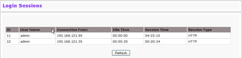
The Login Session page has the following read‐only fields:
Login Session Fields
Field |
Description |
|---|---|
ID |
Identifies the ID of this row. |
User Name |
Shows the user name of the user who is currently logged on to the switch. |
Connection From |
Shows the IP address of the system from which the user is connected. If the connection is a local serial connection, the Connection From field entry is EIA-232. |
Idle Time |
Shows the idle session time. |
Session Time |
Shows the total session time. |
Session Type |
Shows the type of session, which can be Telnet, Serial Port, HTTP, or SSH. |
Click Refresh to update the information on the screen.
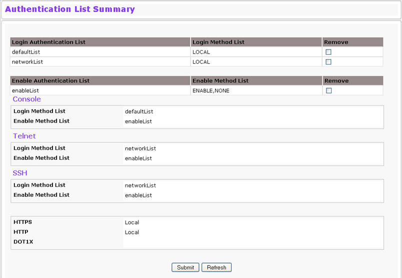
Use the Authentication List Summary page to view information about the authentication lists on the system.
Authentication List Summary
Field |
Description |
|---|---|
Login Authentication List |
Shows the Login authentication profiles. |
Enable Authentication List |
Shows the Enable authentication profiles. |
NOTE: Authentication profiles are also shown for: Console Telnet, SSH, HTTPS, HTTP and 802.1x |
|
Login/Enable Method List |
User authentication methods. Possible options are:
|
Remove |
Removes the authentication profile when checked. |
Exec Accounting List |
Shows the Exec accounting list. |
Exec Method List |
Shows the accounting methods for the Exec list. Possible options are:
|
Command Accounting List |
Shows the Command accounting list. |
Command Method List |
Shows the accounting methods for the Command list. Possible options are:
|
Enable Authentication List |
Shows the Enable authentication profiles. |
Console/Telnet/SSH |
Shows the Exec and Command Accounting Method Lists configured for each List of Console, Telnet, SSH are displayed respectively. |
The page has the following command buttons:
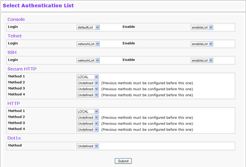
Use the Select Authentication List Configuration page to configure authentication methods for session logins. To access the Select Authentication List page, click System > Configuration > Select Authentication List in the navigation menu.
Select Authentication List Fields
Field |
Description |
|---|---|
Console |
Authentication profiles used to authenticate console users. |
Telnet |
Authentication profiles used to authenticate Telnet users. |
Secure Telnet (SSH) |
Authentication profiles used to authenticate Secure Shell (SSH) users. SSH provides clients secure and encrypted remote connections to a device. |
HTTP and Secure HTTP |
Authentication method used for HTTP access and Secure HTTP access, respectively. Possible field values are:
|
DOT1X |
Authentication method used for Dot1x access. Possible field values are:
|
Command Button
The page has the following command button:
Use the Select Accounting List Configuration page to select the Exec list and Commands list to use to account for user activity associated with the list. To access the Select Authentication List page, click System > Configuration > Select Accounting List in the navigation menu.
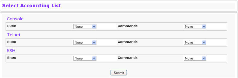
Select Accounting List Fields
Field |
Description |
|---|---|
Console |
Select the Exec and Command list used to record activity for console users. |
Telnet |
Select the Exec and Command list used to record activity for Telnet users. |
Secure Telnet (SSH) |
Select the Exec and Command list used to record activity for Secure Shell (SSH) users. SSH provides clients secure and encrypted remote connections to a device. |
Command Button
The page has the following command button:
Use the Line Password page to configure line mode passwords. To display the page, click System > Configuration > Line Password in the navigation menu.
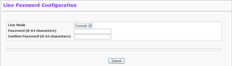
Line Password Fields
Field |
Description |
|---|---|
Line Mode |
Select the Line Mode from the drop‐down list. |
Line Password (8-64 characters) |
The line password for accessing the device via a console, Telnet, or Secure Telnet session. |
Confirm Password (8-64 characters) |
Confirms the new line password. The password appears in the ***** format. |
If you change any data, click Submit to apply the changes to the system. If you want the switch to retain the new values across a power cycle, you must perform a save.
Use the Enable Password page to configure the enable password. To display the page, click System > Configuration > Enable Password in the navigation menu.
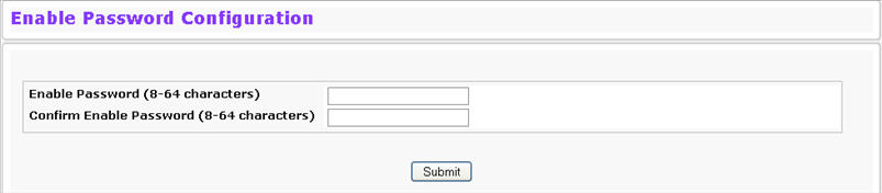
Enable Password Fields
Field |
Description |
|---|---|
Enable Password (8-64 characters) |
The enable password is for accessing the device through a console, Telnet, or Secure Telnet session. |
Confirm Enable Password (8-64 characters) |
Confirms the new enable password. The password appears in the ***** format. |
If you change any data, click Submit to apply the changes to the system. If you want the switch to retain the new values across a power cycle, you must perform a save.
Use this page to configure settings that apply to all user passwords. To display the page, click Configuration > Password Management in the navigation menu.
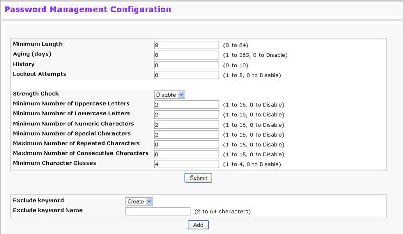
Password Management Configuration Fields
Field |
Description |
|---|---|
Minimum Length |
Passwords must have at least this many characters (8 to 64). |
Aging (days) |
Passwords will expire this many days after creation. |
History |
Users cannot reuse previous passwords up to this number. |
Lockout Attempts |
After a user fails to log in this number of times, the user is locked out until the password is reset by the administrator. |
Strength Check |
Enable or disable the password strength check feature. Enabling this feature forces the user to configure passwords that comply with the strong password configuration specified in the following fields. |
Minimum Number of Uppercase Letters |
Specify the minimum number of uppercase letters a password must include. |
Minimum Number of Lowercase Letters |
Specify the minimum number of lowercase letters a password must include. |
Minimum Number of Numeric Characters |
Specify the minimum number of numbers a password must include. |
Minimum Number of Special Characters |
Specify the minimum number of special characters (non‐alphanumeric, such as # or &) a password must include |
Maximum Number of Repeated Characters |
Specify the maximum number of repeated characters a password is allowed to include. An example of four repeated characters is aaaa. |
Maximum Number of Consecutive Characters |
Specify the maximum number of consecutive characters a password is allowed to include. An example of four consecutive characters is abcd |
Minimum Character Classes |
Specify the minimum number of character classes a password must contain. There are four character classes:
|
Exclude Keyword |
The password to be configured should not contain the keyword mentioned in this field. The valid range for the keyword is (2 to 64) characters in length. |
Exclude Keyword Name |
This field appears only on selection of create option from 'Exclude Keyword' combo box. The valid range for the keyword is (2 to 64) characters in length. |
If you change any data, click Submit to apply the changes to the system. If you want the switch to retain the new values across a power cycle, you must perform a save.
Use the Last Password Result page view information about the last attempt to set a user password. If the password set was unsuccessful, a reason for the failure is given. To display the page, click System > Configuration > Last Password Result in the navigation menu.
Last Password Result
Field |
Description |
|---|---|
Last Password Set Result |
Shows the results of the most recent attempt to set a password. |
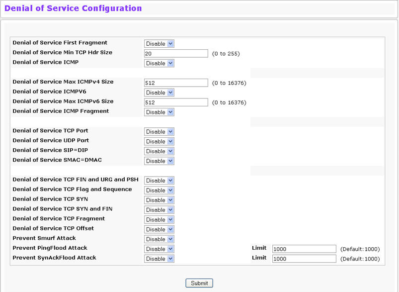
Use the Denial of Service (DoS) page to configure DoS control. TejNOS-EN software provides support for classifying and blocking specific types of DoS attacks. You can configure your system to monitor and block these types of attacks:
NOTE: Monitoring and blocking of the types of attacks listed below are supported only on the following platforms:
BCM56514
BCM56624
BCM56820
BCM56224
BCM56634
BCM56636
To access the Denial of Service page, click System > Configuration > Denial of Service in the navigation menu.
Denial of Service Configuration Fields
Field |
Description |
|---|---|
Denial of Service First Fragment |
Enable or disable this option by selecting the corresponding line on the pulldown entry field. Enabling First Fragment DoS prevention causes the switch to drop packets that have a TCP header smaller then the configured Min TCP Hdr Size. The factory default is disabled. |
Denial of Service Min TCP Hdr Size |
Specify the Min TCP Hdr Size allowed. If First Fragment DoS prevention is enabled, the switch will drop packets that have a TCP header smaller then this configured Min TCP Hdr Size. The factory default is disabled. |
Denial of Service ICMP |
Enable or disable this option by selecting the corresponding line on the pulldown entry field. Enabling ICMP DoS prevention causes the switch to drop ICMP packets that have a type set to ECHO_REQ (ping) and a size greater than the configured ICMP Pkt Size. The factory default is disabled. |
Denial of Service SIP=DIP |
Enable or disable this option by selecting the corresponding line on the pulldown entry field. Enabling SIP=DIP DoS prevention causes the switch to drop packets that have a source IP address equal to the destination IP address. The factory default is disabled. |
Denial of Service TCP Fragment |
Enable or disable this option by selecting the corresponding line on the pulldown entry field. Enabling TCP Fragment DoS prevention causes the switch to drop packets that have an IP fragment offset equal to 1. The factory default is disabled. |
Prevent Smurf Attack |
Enable or disable this option by selecting the corresponding line on the pulldown entry field. Enabling Smurf Attack prevention causes the switch to not respond to spoofed broadcast ping messages. The factory default is disabled. |
Prevent PingFlood Attack |
Enable or disable this option by selecting the corresponding line on the pulldown entry field. Enabling Ping Flood prevention causes the switch to reply to the number of ping messages specified in the Limit field. The switch will not respond to pings after the limit is reached. The factory default is disabled. |
Prevent SynAckFlood Attack |
Enable or disable this option by selecting the corresponding line on the pulldown entry field. Enabling SynAck Flood prevention causes the switch to reply to the number of SYN messages specified in the Limit field. The switch will not respond to SYN messages after the limit is reached. The factory default is disabled. |
NOTE: The following fields are supported on the BCM56514, BCM56624, BCM56820, BCM56224, BCM56634, and BCM56636 platforms. |
|
Denial of Service Max ICMPv4 Pkt Size |
Specify the Max ICMPv4 Pkt Size allowed. If ICMP DoS prevention is enabled, the switch will drop IPv4 ICMP ping packets that have a size greater than this configured Max ICMP Pkt Size. The factory default is disabled. |
Denial of Service Max ICMPv6 Pkt Size |
Specify the Max ICMPv6 ICMP Pkt Size allowed. If ICMP DoS prevention is enabled, the switch will drop IPv6 ICMP ping packets that have a size greater than this configured Max ICMP Pkt Size. The factory default is disabled. |
Denial of Service ICMP Fragment |
Enable or disable this option by selecting the corresponding line on the pulldown entry field. Enabling ICMP Fragment DoS prevention causes the switch to drop ICMP Fragmented packets. The factory default is disabled. |
Denial of Service TCP Port |
Enable or disable this option by selecting the corresponding line on the pulldown entry field. Enabling TCP Port DoS prevention causes the switch to drop packets that have TCP source port equal to TCP destination port. The factory default is disabled. |
Denial of Service TCP Port |
Enable or disable this option by selecting the corresponding line on the pulldown entry field. Enabling TCP Port DoS prevention causes the switch to drop packets that have TCP source port equal to TCP destination port. The factory default is disabled. |
Denial of Service UDP Port |
Enable or disable this option by selecting the corresponding line on the pulldown entry field. Enabling UDP Port DoS prevention causes the switch to drop packets that have UDP source port equal to UDP destination port. The factory default is disabled. |
Denial of Service SMAC=DMAC |
Enable or disable this option by selecting the corresponding line on the pulldown entry field. Enabling SMAC=DMAC DoS prevention causes the switch to drop packets that have a source MAC address equal to the destination MAC address. The factory default is disabled. |
Denial of Service TCP FIN and URG and PSH |
Enable or disable this option by selecting the corresponding line on the pulldown entry field. Enabling TCP FIN & URG & PSH DoS prevention causes the switch to drop packets that have TCP flags FIN, URG, and PSH set and TCP Sequence Number = 0. The factory default is disabled. |
Denial of Service TCP Flag and Sequence |
Enable or disable this option by selecting the corresponding line on the pulldown entry field. Enabling TCP Flag DoS prevention causes the switch to drop packets that have TCP control flags set to 0 and TCP sequence number set to 0. The factory default is disabled. |
Denial of Service TCP SYN |
Enable or disable this option by selecting the corresponding line on the pulldown entry field. Enabling TCP SYN DoS prevention causes the switch to drop packets that have TCP Flags SYN set. The factory default is disabled. |
Denial of Service TCP SYN&FIN |
Enable or disable this option by selecting the corresponding line on the pulldown entry field. Enabling TCP SYN & FIN DoS prevention causes the switch to drop packets that have TCP Flags SYN and FIN set. The factory default is disabled. |
Denial of Service TCP Offset |
Enable or disable this option by selecting the corresponding line on the pulldown entry field. Enabling TCP Offset DoS prevention causes the switch to drop packets that have a TCP header Offset equal to 1. The factory default is disabled. |
If you change any of the DoS settings, click Submit to apply the changes to the switch. To preserve the changes across a switch reboot, you must perform a save.
Use the Internal Authentication Server Users Configuration page to add users to the Internal Authentication Server (IAS) database. The IAS database is a dedicated internal database is for local authentication of users for network access through the IEEE 802.1X feature. The maximum number of users in the IAS database is 100. You can create a text file that contains a list of IAS users to add to the database and then download the file to the switch. The following script is an example of an IAS user text file that contains three users:
configure
aaa ias‐user username client‐1
password my‐password1
exit
aaa ias‐user username client‐2
password aa5c6c251fe374d5e306c62496c3bcf6 encrypted
exit
aaa ias‐user username client‐3
password 1f3ccb1157
exit
After the download completes, client‐1, client‐2, and client‐3 are added to the IAS database. The password for client‐2 is encrypted. When Dot1x authentication is enabled on the ports and the authentication method is LOCAL, port access is allowed only to users in this database that provide the correct name and password.
To access the Internal Authentication Server Users Configuration page, click System > Configuration > Internal Authentication Server Users Configuration in the navigation menu.
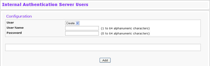
Internal Authentication Server Users Configuration Fields
Field |
Description |
|---|---|
User |
From the User menu, select an existing user to configure, or select Create to create a new IAS user. |
User Name |
Specify the name of the user. User names are up to 32 alphanumeric characters in length and are not case sensitive. Valid characters include all the alphanumeric characters and the dash ('-') and underscore ('_') characters |
Password |
Enter the new or changed password for the account. Passwords must be greater than eight characters and can be up to 64 characters in length, and are case sensitive. Special characters are permitted. |
Click Submit to apply the changes to the system. You must perform a save to make the changes persist across a reboot.
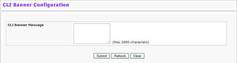
Use the CLI Banner Configuration page to configure a message that appears before the user prompt as a Prelogin banner. The message configured shows up on Telnet, SSH and Console connections.
To access the CLI Banner Configuration page, click System > Configuration > CLI Banner Configuration in the navigation menu.
CLI Banner Configuration Fields
Field |
Description |
|---|---|
CLI Banner Message |
Specify the message that users see when they log on to the switch by using the CLI. |
Click Submit to apply the changes to the system. You must perform a save to make the changes persist across a reboot.