![]()
![]()
![]()
![]()
|
|
|
|
|
The CEF-5 card supports the following operational modes:
This 2*10G + 12*1G is the default, non-license based mode available when the card is jacked-in the chassis. Two XFP ports P3 and P4 and four SFP+ ports P13 to P16 are not usable in this mode.
This 6*10G + 12*1G is a license based mode. Two SFP+ ports namely P13 and P14 not usable in this mode.
This 8*10G is a license based mode. SFP ports P5 to P12 and RJ45 ports P17 to P20 are not usable in this mode.
There are two separate licenses available namely,
For more information on how to enable a licensed feature, refer to the topic Enabling Licensed Feature.
Viewing Card Details
Perform the steps given below to view the CEF-5 card details.
OR
Click System > Node slot view in the navigation pane. The Node slot view preview pane is displayed. Click on CEF-5 card.
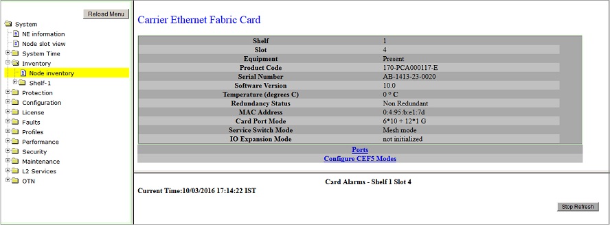
Ports link direct you to Ports on Card Shelf :1 Slot: <number> preview pane.
Configure CEF5 Modes link directs you to EoS/EoPDH Card Configuration - CEF-5-1-<slot number> preview pane and allows you to configure the CEF-5 card port mode.
Card Configuration
Perform the steps given below to configure CEF-5 card port mode.
OR
Click System > Node slot view in the navigation pane. The Node slot view preview pane is displayed. Click on CEF-5 card.
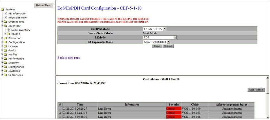
NOTE: CEM and SATOP_AND_CESOPSN options are not supported in this product release.
The CEF-5 is configured with the desired values.
NOTE 1: Parameter IO Expansion Mode is not supported in this product release.
NOTE 2: Only one combination of slots 2, 3, 4 or 8, 9, 10 can be in Mesh mode. The combination configured first will be in Mesh mode, by default. The Mesh combination 2, 3, 4 will be displayed as ServiceSwitch-16 and 8, 9, 10 will be displayed as ServiceSwitch-17. The other slots 1, 7, 11 will be in standalone mode.
NOTE 3: CEF-5 supports STM-8 worth of lower order connections i.e. VC12 on HCPXCC04 card.
Changing CEF-5 CardPortMode
Perform the steps given below to change the CEF-5 CardPortMode from '6*10G + 12*1G' to '8*10G' mode.