Previous Topic

Next Topic

Book Contents

Book Index

Configuring HCPSLine22 Card

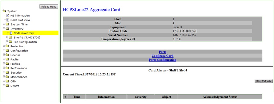
After jacking-in HCPSLine22 card into the system, the card configuration has to be performed followed by port configuration; procedures for which are covered below. HCPSLine22 card is supported on HCPXCC04 cross-connect card.

Viewing Card Details

Perform the steps given below to view the HCPSLine22 card details.

  1. Click Inventory > Node inventory in the navigation pane. The Node Inventory preview pane is displayed. Click on the Slot 'number' corresponding to the HCPSLine22 Card Label.

    OR

    Click System > Node slot view in the navigation pane. The Node slot view preview pane is displayed. Click on HCPSLine22 card.

  2. HCPSLine22 Intelligent Card preview pane is displayed as shown in the figure below. For parameter description, refer to the topic Viewing Card Parameters.

    Ports link will direct you to Ports on Card Shelf :1 Slot: <number> preview pane which displays the details of ports on the card.

    Configure Card link will direct you to AGGNX100G Card configuration - HCPSLine22-1-<slot number> preview pane where you can configure the card mode.

    Ports Configuration link will direct you to AGGNX100G Ports Configuration - HCPSLine22-1-<slot number> preview pane where you can configure the add/drop ports on the card.

    HCPSLine22 Intelligent Card pane

Card Configuration

On fresh jack-in, the HCPSLine22 card will be in 'NONE' mode by default. Perform the steps given below to configure the card in desired mode.

  1. Click Inventory > Node inventory in the navigation pane. The Node Inventory preview pane is displayed. Click on the Slot 'number' corresponding to the HCPSLine22 Card Label.

    OR

    Click System > Node slot view in the navigation pane. The Node slot view preview pane is displayed. Click on HCPSLine22 card.

  2. On HCPSLine22 Intelligent Card preview pane, click on Configure Card link. The AGGNX100G Card configuration - HCPSLine22-1-<slot number> preview pane is displayed.

    Card configuration- HCPSLine22 Card

  3. Click on Card Configuration drop down option and select the desired card mode. For more information on card modes, refer to the table Card Configuration mode- HCPSLine22 card given below.
  4. Click Submit. A confirmation message is displayed.
  5. Click Accept Valid Modifications. A "Successfully Modified" message is displayed under the Warnings field.

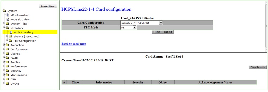
    Back link will direct you to AGGNX100G Card configuration - HCPSLine22-1-<slot number> preview pane.

Card Configuration mode- HCPSLine22 card

Parameter

Description

Card Configuration


None

It is the default mode when the card is freshly jacked-in to the system.

1x100G OTN TRIBUTARY

Card provides single 100G port P1 of OTU4 capacity. The logical ODU4k interface of OTU4 port can be channelized to ODU0, ODU1, ODU2, ODU2e, ODU3 rate channels for provisioning ODU connections.

NOTE: The mode is not supported for this release.

10x10G TO 1xOTU4 MUXPONDER

Card provides one 100G port P11 of OTU4 capacity and 10 ports P1 to P10 configurable to None, STM64, OTU2 or 10GE-LAN.

  • STM64 and 10GE-LAN works only in TTM mode. The logical interface ODU4k of OTU4 port cannot be channelized.
  • In muxponder mode, ports P1 to P10 act as Client Port that are one to one mapped to the Time Slots on the Network Port OTU4 (P11) on the same card. For instance, port P1 is mapped to 1 to 8 Time Slots on port P11; similarly port P2 is mapped to next eight Time Slots 9 to 16.

10x10G OTN TRIBUTARY

Card provides 10 ports P1 to P10, each port configurable to None, STM64, OTU2, OTU2e, 10GE-LAN, or OTU1e.

  • STM64 and 10GE-LAN can be used only with Timing-Transparent-Mapping, where these ports associate with logical ODU2k and ODU2ek interface respectively that can be used to carry non-OTN Client signals.
  • Logical ODU2k interface of OTU2 port can be channelized to ODU0 and ODU1 rate; the logical ODU2ek interface of OTU2e port can be channelized to ODU0, ODU1, ODU2, ODU3, and ODU2e rate channels for provisioning ODU connections.

NOTE: The mode is not supported for this release.

10x10G SDH FLEXI

Card provides 10 ports P1 to P10, each port configurable to None, STM64, or 10GE-LAN.

  • STM64 with No Timing-Transparent-Mapping can be used for normal cross-connect provisioning.
  • STM64 and 10GE-LAN with Timing Transparent-Mapping will associate with logical ODU2k and ODU2ek interface respectively that can be used carry non-OTN Client signals.


Port Configuration

After configuring the HCPSLine22 card mode, the Add/Drop ports on the card have to be configured. Perform the steps given below to configure the ports on HCPSLine22 card.

  1. Click Inventory > Node inventory in the navigation pane. The Node Inventory preview pane is displayed. Click on the Slot 'number' corresponding to the HCPSLine22 Card Label.

    OR

    Click System > Node slot view in the navigation pane. The Node slot view preview pane is displayed. Click on HCPSLine22 card.

  2. On HCPSLine22 Intelligent Card preview pane, click on Ports Configuration link. The AGGNX100G Ports Configuration - HCPSLine22-1-<slot number> preview pane is displayed. The number of ports displayed under AddDrop Port Configuration will vary depending on card configuration mode selected by the user. Figure below shows the Ports Configuration pane when HCPSLine22 card is in '10x10G OTN TRIBUTARY' mode.

    Ports Configuration- HCPSLine22 card

  3. Under Add Drop Port Configuration field, click on PortConfiguration for Port No<n> drop down option and select the desired port mode. Refer to the table Card Configuration mode- HCPSLine22 card for the port modes supported for different card modes.

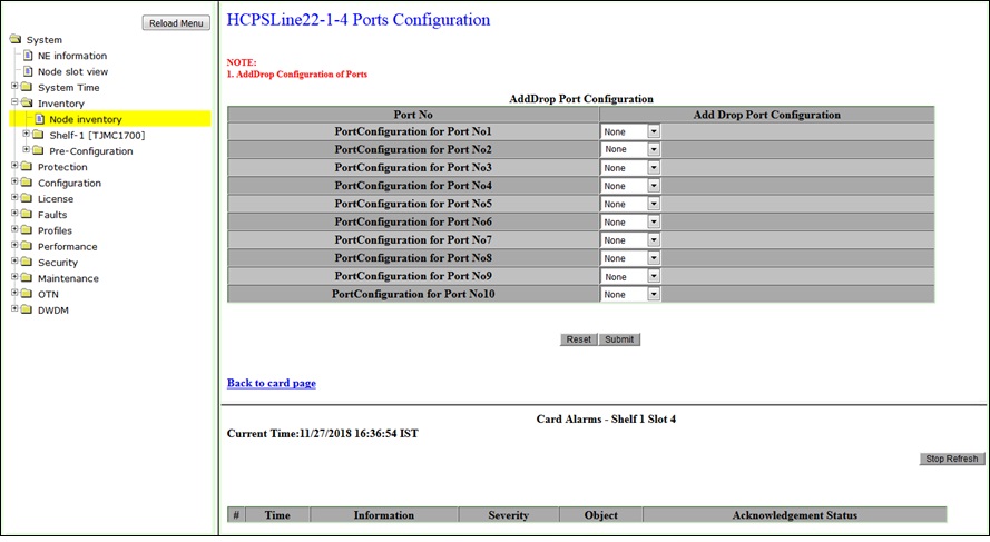
    NOTE: Only one port can be configured or changed at a time.

  4. Click Submit. A "SUCCESS" message is displayed. Setting port configuration for HCPSLine22 card is succeeded.

    Back to card page link will direct you to HCPSLine22 Intelligent Card preview pane.

See Also

Working With Inventory Menu

Viewing Node Inventory

Deleting Card Configurations

Deleting Pluggable Modules

Shelf Sub-menu

Rack Shelf Sub-menu

Pre-Configuration

Viewing Laser Details

Viewing and Editing Laser Details

Viewing CFP Laser Details

Editing CFP Laser Details

Configuring HCPSLine01 Card

Configuring HCPULine01 Card

Configuring HCPSLine03 Card

Configuring HCPSLine08 Card

Configuring CEF-5 Modes

Performing Forced Switch Over

Force Recovery on CEL-3 Card

Working with Optical Adapter Card

Working with Optical Fiber Amplifier Card

Working with FPU01 card