![]()
![]()
![]()
![]()
|
|
|
|
|
Fiber Protection Unit (HCPFPU01) card allows you to provide signal protection against optical fiber line failures. The card will switch to protection path on detecting loss of optical power or when it decreases below the set threshold.
In the FPU Card Information preview pane, you can:
Viewing Card Information
Perform the steps given below to view the HCPFPU01 card details.
OR
Click System > Node slot view in the navigation pane. The Node slot view preview pane is displayed. Click on HCPADP01 card.
Editing Card parameters and Issuing External Request
Perform the steps given below to set the HCPFPU01 card parameters and issue external request.
OR
Click System > Node slot view in the navigation pane. The Node slot view preview pane is displayed. Click on HCPADP01 card.
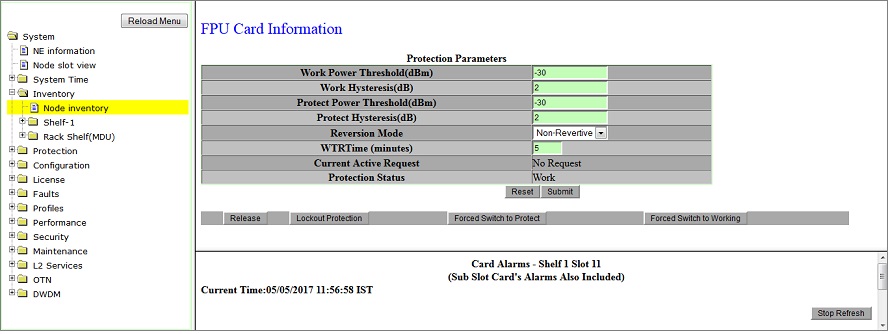
Protection Parameters
Parameter |
Description |
Default Value |
Acceptable Values |
|---|---|---|---|
Work Power Threshold (dBm) |
Enter the threshold value for power at Work port beyond which protection switching will happen. |
-30 |
Work threshold +/- hysteresis range should be between 2dB and -38dB |
Work Hysteresis (dB) |
Work hysteresis value will determine the switching of the signal back to Work path after the fault is restored i.e. Work threshold value +/- Work Hysteresis value. |
2 |
Work threshold +/- hysteresis range should be between 2dB and -38dB |
Protect Power Threshold (dBm) |
Enter the threshold value for power at Protect port beyond which switching will happen. |
-30 |
Protect threshold +/- hysteresis range should be between 2dB and -38dB |
Protect Hysteresis (dB) |
Protect hysteresis value will determine the switching of the signal to Protect path i.e. Protect threshold value +/- Protect Hysteresis value. |
2 |
Protect threshold +/- hysteresis range should be between 2dB and -38dB |
Reversion Mode |
Allows you to select the mode of reversion as:
|
Non-Revertive |
|
WTRTime (minutes) |
Enter the time interval (in minutes) after which the traffic must switch back to work channel upon rectification of work channel, when reversion mode is set as revertive. |
5 |
1 to 12 |
Current Active Request |
Displays the current request on the path. |
No Request |
-- |
Protection Status |
Displays the active channel in which traffic is being currently carried. |
Work |
-- |
External Requests
Parameters |
Description |
|---|---|
Release |
Clears previously set commands. |
Locked Protection |
Prevents traffic from switching to protect path. |
Forced Switch to Protect |
Forces signal to switch to the protect path. |
Forced Switch to Working |
Forces signal to switch to the work path. |