![]()
![]()
![]()
![]()
|
|
|
|
|
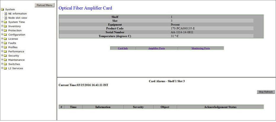
In the Optical Fiber Amplifier Card preview pane, you can:
Viewing Optical Fiber Amplifier Card
Perform the steps given below to view the Optical Fiber Amplifier Card preview pane.
OR
Click System > Node slot view in the navigation pane. The Node slot view preview pane is displayed. Click on an OFA card.
Viewing and Editing Card Information
Perform the steps given below to view and edit the Optical Fiber Amplifier (OFA) card details.
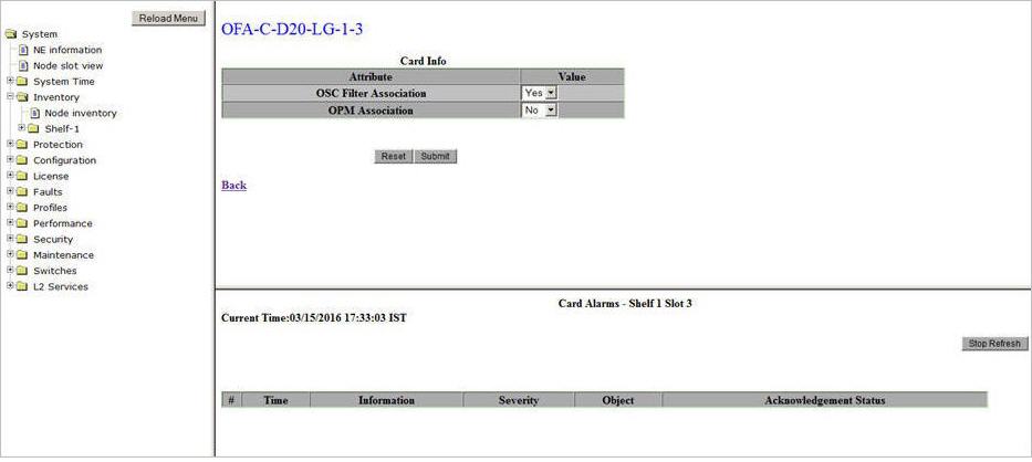
The OSC filter is a passive module plugged into an OFA card and has single or dual add and drop ports. It supports add and drop of supervisory channel wavelength, primarily at intermediate line amplifier (ILA) sites.
The Optical Power Monitoring card is connected through the monitoring port on OFA card for optical power read out of up to 80 Channels at 50GHz intervals.
A click on Back link will direct you to the Card Info of the OFA card.
Viewing and Editing Amplifier Port Details
The number of amplifier ports on an OFA card depends on its version. For example, OFA-C-S17-FG (single version) has one Amplifier port while OFA-C-D17-FG (dual version) has two Amplifier ports on the front panel of the card.
Perform the steps given below to view and edit the amplifier port details on an OFA card.
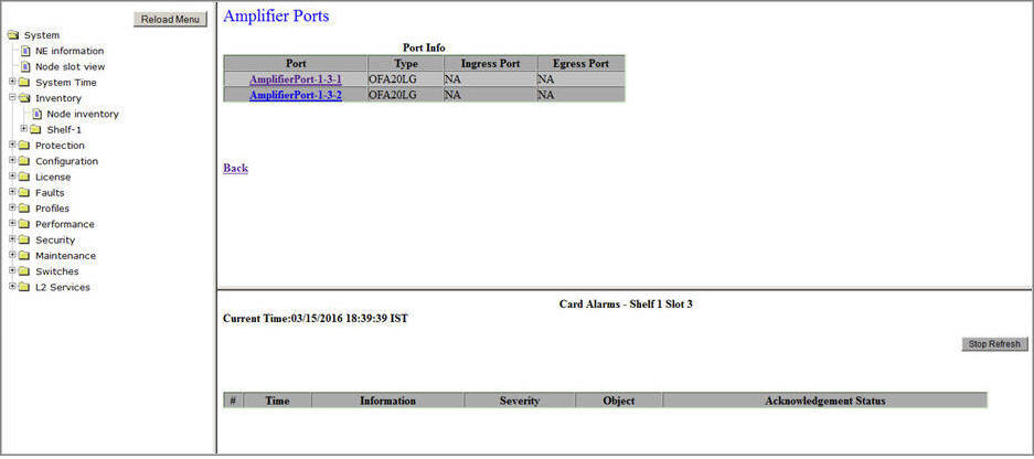
A click on Back link will direct you to the Port Info page of the Amplifier port.
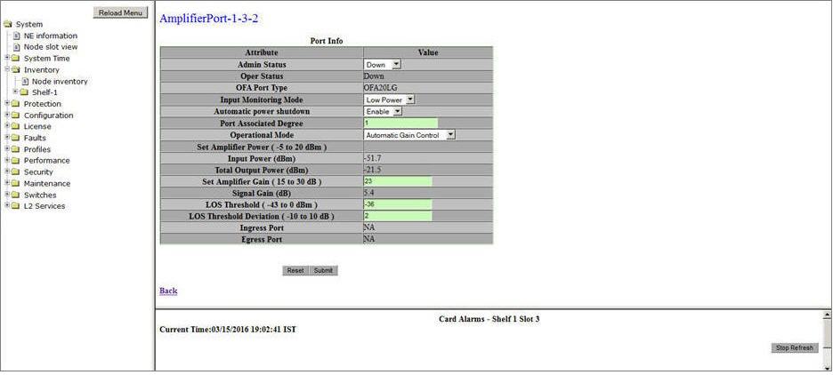
Amplifier Port Info- OFA Card
Parameter |
Description |
Default Value |
Acceptable Values |
|---|---|---|---|
Admin Status |
Select the transmitting status of the port from the drop down list. |
Down |
|
Oper Status |
Displays the receiving or link status of the port as Up or Down. |
-- |
-- |
OFA Port Type |
Displays the version of OFA. |
-- |
-- |
Input Monitoring Mode |
This parameter is applicable for HG and LG variant of OFA.
|
Low Power |
|
Automatic power shutdown |
Select the desired option from the drop down menu.
|
Enable |
|
Port Associated Degree |
Allows you to enter an identifier for the amplifier port. |
1 |
1 to 8 |
Operational Mode |
Allows you to select the operational mode of the amplifier.
It is recommended to select the 'Operational Mode' as 'Automatic Gain Control'. |
Automatic Gain Control |
|
Set Amplifier Power (-5 to 20 dBm) |
This parameter is editable only when the Operational Mode is selected as APC. Enter the input power threshold for the amplifier. |
0 |
-5 to 20 dBm |
Set Amplifier Tilt (dB) |
This parameter is applicable only for variable gain amplifiers. It is calculated by LMS (tilt of the least mean squares fitted line) of the gain spectrum; considering all channels' gain. Negative tilt means that longer wavelengths have Lower gain whereas a positive tilt means longer wavelengths have higher gain values. |
0 |
+2 to -2 |
Mid Stage Access Loss(dB) |
This parameter is applicable only for mid stage access type of amplifiers. Displays the loss or attenuation introduced in the signal after dispersion compensation. The value should be less than 8 dBm. |
-- |
-- |
Input Power (dBm) |
Displays the input power to the amplifier. |
-- |
-- |
Total Output Power (dBm) |
Displays the output power from the amplifier. |
-- |
-- |
Set Amplifier Gain (15 to 30 dB) |
Enter the gain expected to achieve from the amplifier. This parameter is editable only when the Operational Mode is selected as AGC. |
23 |
15 to 30 dB |
Signal Gain (dB) |
Displays the gain achieved from the amplifier. |
-- |
-- |
LOS Threshold (-43 to 0 dBm) |
Enter a threshold value for input power if beyond which is crossed, an alarm is raised. |
-36 |
-43 to 0 dBm |
LOS Threshold Deviation (-10 to 10 dB) |
Enter the threshold deviation value for input power at which the alarm is cleared. |
2 |
-10 to 10 dB |
Ingress Port |
A link to the port on remote end to which the Rx of the Amplifier port is connected and receiving the signal. The link is displayed only when a port connect is added between the source and the destination. |
NA |
-- |
Egress Port |
A link to the port on remote end to which the Tx of the Amplifier port is connected and transmitting the signal. The link is displayed only when a port connect is added between the source and the destination. |
NA |
-- |
NOTE: If the user chooses Automatic Gain Control, then Set Amplifier Power option will be grayed out. Similarly, when Automatic Power Control is selected, Set Amplifier Gain will be grayed out. |
|||
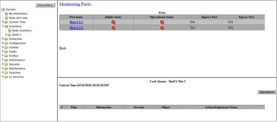
Viewing Monitoring Ports Information
Perform the steps given below to view the details of Monitor port on an OFA card.
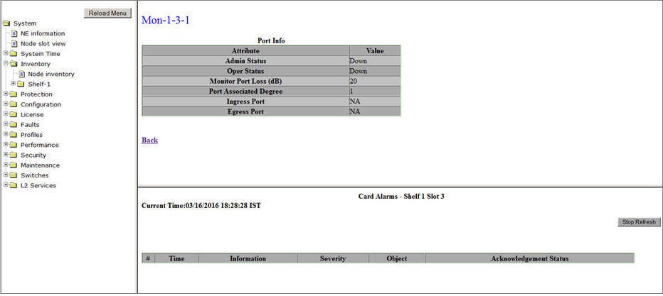
Monitor Port Info
Parameter |
Description |
|---|---|
Admin Status |
Displays the transmitting status of the port as Up or Down. |
Oper Status |
Displays the receiving status of the port or link status as Up or Down. |
Monitor Port Loss (dB) |
Displays the power loss at monitor port in terms of dB. Monitor Port Loss is generally configured as 1% tap of output. |
Port Associated Degree |
Displays the user defined identifier for the port. |
Ingress Port |
A link to the port on OPM card to which the Rx of the Monitor port is connected and receiving the signal. The link is displayed only when a port connect is added between the source and the destination. |
Egress Port |
This parameter is not applicable and the value will be displayed as NA. |
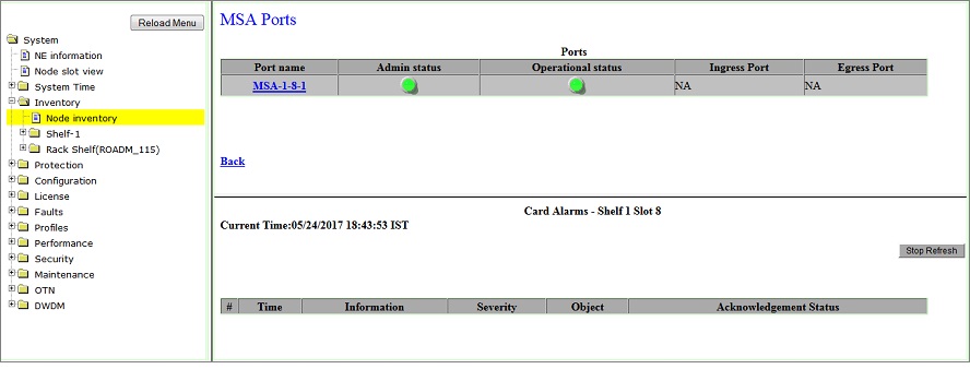
Viewing MSA Port Information
The MSA Ports link will be displayed on Optical Fiber Amplifier Card preview pane of Mid Stage Access type of Amplifiers.
Perform the steps given below to view the details of MSA port on an OFA card.
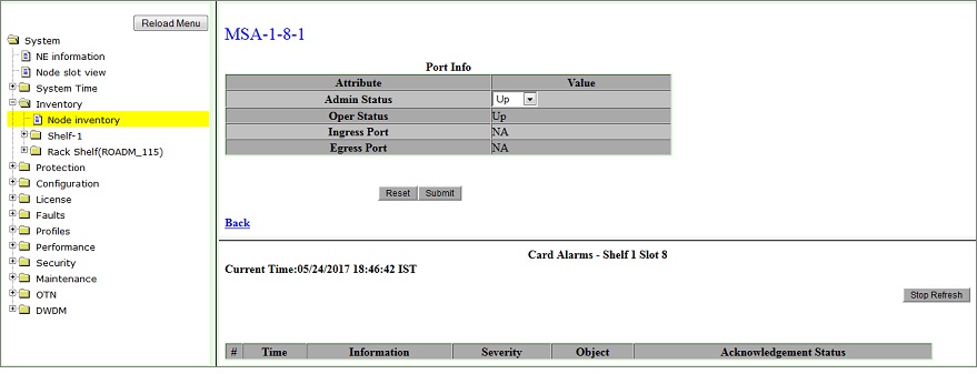
MSA Port Info- Mid Stage Access OFA
Parameter |
Description |
|---|---|
Admin Status |
Select the transmitting status of the port as Up or Down. |
Oper Status |
Displays the receiving status of the port or link status as Up or Down. |
Ingress Port |
A link to the port to which the Rx of the MSA port is connected and receiving the signal. The link is displayed only when a port connect is added between the source and the destination. |
Egress Port |
This parameter is not applicable and the value will be displayed as NA. |