![]()
![]()
![]()
![]()
|
|
|
|
|
DHCP snooping is a security feature that monitors DHCP messages between a DHCP client and DHCP servers to filter harmful DHCP messages and to build a bindings database of {MAC address, IP address, VLAN ID, port} tuples that are considered authorized. You can enable DHCP snooping globally and on specific VLANs, and configure ports within the VLAN to be trusted or untrusted. DHCP servers must be reached through trusted ports. DHCP snooping enforces the following security rules:
The hardware identifies all incoming DHCP packets on ports where DHCP snooping is enabled. DHCP snooping is enabled on a port if (a) DHCP snooping is enabled globally, and (b) the port is a member of a VLAN where DHCP snooping is enabled. On untrusted ports, the hardware traps all incoming DHCP packets to the CPU. On trusted ports, the hardware forwards client messages and copies server messages to the CPU so that DHCP snooping can learn the binding.
To access the DHCP Snooping Configuration page, click Switching > DHCP Snooping > Configuration.
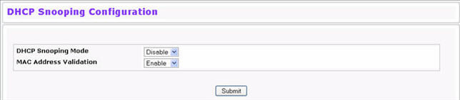
DHCP Snooping Configuration
Field |
Description |
|---|---|
DHCP Snooping Mode |
Enables or disables the DHCP Snooping feature. The default is Disable. |
MAC Address Validation |
Enables or disables the validation of sender MAC Address for DHCP Snooping. The default is Enable. |
Click Submit to apply the new configuration and cause the change to take effect. These changes will not be retained across a power cycle unless a Save configuration is performed.
The DHCP snooping application does not forward server messages because they are forwarded in hardware. DHCP snooping forwards valid DHCP client messages received on non-routing VLANs. The message is forwarded on all trusted interfaces in the VLAN.
DHCP snooping can be configured on switching VLANs and routing VLANs. When a DHCP packet is received on a routing VLAN, the DHCP snooping application applies its filtering rules and updates the bindings database. If a client message passes filtering rules, the message is placed into the software forwarding path, where it may be processed by the DHCP relay agent, the local DHCP server, or forwarded as an IP packet. DHCP snooping is disabled globally and on all VLANs by default. Ports are untrusted by default.
To access the DHCP Snooping VLAN Configuration page, click Switching > DHCP Snooping > VLAN Configuration in the navigation menu.
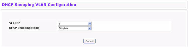
DHCP Snooping VLAN Configuration
Field |
Description |
|---|---|
VLAN ID |
Select the VLAN for which information to be displayed or configured for the DHCP snooping application. |
DHCP Snooping Mode |
Enables or disables the DHCP snooping feature on the selected VLAN. The default is Disable. |
Click Submit to apply the new configuration and cause the change to take effect. These changes will not be retained across a power cycle unless a Save configuration is performed.
The hardware rate limits DHCP packets sent to the CPU from untrusted interfaces to 64 kbps. There is no hardware rate limiting on trusted interfaces.
To prevent DHCP packets from being used as a DoS attack when DHCP snooping is enabled, the snooping application enforces a rate limit for DHCP packets received on untrusted interfaces. DHCP snooping monitors the receive rate on each interface separately. If the receive rate exceeds the configuration limit, DHCP snooping brings down the interface. You must do “no shutdown” on this interface to further work with that port. You can configure both the rate and the burst interval.
The DHCP snooping application processes incoming DHCP messages. For DHCPRELEASE and DHCPDECLINE messages, the application compares the receive interface and VLAN with the client’s interface and VLAN in the binding database. If the interfaces do not match, the application logs the event and drops the message. For valid client messages, DHCP snooping compares the source MAC address to the DHCP client hardware address. Where there is a mismatch, DHCP snooping logs and drops the packet. You can disable this feature using the DHCP Snooping Interface Configuration page, shown in Figure below, or by using the no ip dhcp snooping verify mac-address command. DHCP snooping forwards valid client messages on trusted members within the VLAN. If DHCP relay and/or DHCP server co-exist with the DHCP snooping, the DHCP client message will be sent to the DHCP relay and/or DHCP server to process further.
To access the DHCP Snooping Interface Configuration page, click Switching > DHCP Snooping > Interface Configuration in the navigation menu.
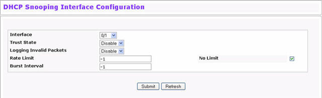
DHCP Snooping Interface Configuration
Field |
Description |
|---|---|
Interface |
Select the interface for which data is to be displayed or configured. |
Trust State |
If it is enabled, the DHCP snooping application considers the port as trusted. The default is Disable. |
Logging Invalid Packets |
If it is enabled, the DHCP snooping application logs invalid packets on this interface. The default is Disable. |
Rate Limit |
Specifies the rate limit value for DHCP snooping purposes. If the incoming rate of DHCP packets exceeds the value of this object for consecutively burst interval seconds, the port will be shutdown. If this value is None, there is no limit. The default is 15 packets per second (pps). The Rate Limit range is 0 to 300. |
Burst Interval |
Specifies the burst interval value for rate limiting purposes on this interface. If the rate limit is None, the burst interval has no meaning and displays it as "N/A". The default is 1 second. The Burst Interval range is 1 to 15. |
Click Submit to apply the new configuration and cause the change to take effect. These changes will not be retained across a power cycle unless a Save configuration is performed.
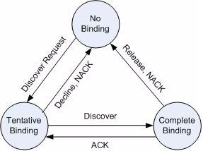
The DHCP snooping application uses DHCP messages to build and maintain the binding’s database. The binding’s database only includes data for clients on untrusted ports. DHCP snooping creates a tentative binding from DHCP DISCOVER and REQUEST messages. Tentative bindings tie a client to a port (the port where the DHCP client message was received). Tentative bindings are completed when DHCP snooping learns the client’s IP address from a DHCP ACK message on a trusted port. DHCP snooping removes bindings in response to DECLINE, RELEASE, and NACK messages. The DHCP snooping application ignores the ACK messages as a reply to the DHCP Inform messages received on trusted ports. You can also enter static bindings into the binding database.
The DHCP binding database is persisted on a configured external server or locally in flash, depending on the user configuration. A row wise checksum is placed in the text file that is going to be stored in the remote configured server. On reloading, the switch reads the configured binding file to build the DHCP snooping database. When the switch starts and the calculated checksum value equals the stored checksum, the switch reads entries from the binding file and populates the binding database. A checksum failure or a connection problem to the external configured server will cause the switch to loose the bindings and will cause a host’s data loss if IP Source Guard (IPSG) and/or DAI is enabled.
When a switch learns of new bindings or when it loses bindings, the switch immediately updates the entries in the database. The switch also updates the entries in the binding file. The frequency at which the file is updated is based on a configurable delay, and the updates are batched.
If the absolute lease time of the snooping database entry expires, that entry is removed. You should take care of the system time to be consistent across the reboots. Otherwise, the snooping entries will not expire properly. If a host sends a DHCP release while the switch is rebooting, when the switch receives the DHCP discovery or request, the client’s binding goes to the tentative binding as shown in Figure below.
To access the DHCP Snooping Static Binding Configuration page, click Switching > DHCP Snooping > Binding Configuration in the navigation menu.
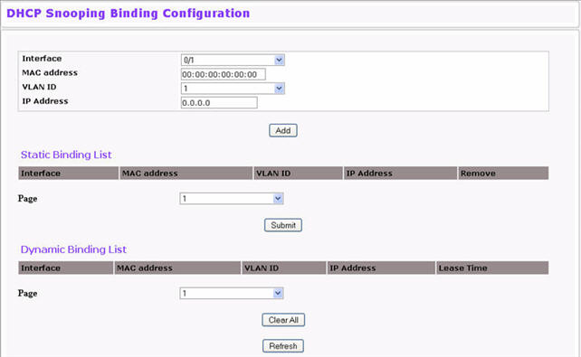
DHCP Snooping Static Binding Configuration
Field |
Description |
|---|---|
Interface |
Select the interface to add a binding into the DHCP snooping database. |
MAC Address |
Specify the MAC address for the binding to be added. This is the Key to the binding database |
VLAN ID |
Select the VLAN from the list for the binding rule. The range of the VLAN ID is 1 to 3965. |
IP Address |
Specify a valid IP address for the binding rule. |
The DHCP snooping static binding list lists all the DHCP snooping static binding entries page by page.
DHCP Snooping Static Binding List
Field |
Description |
|---|---|
Interface |
Displays the interface. |
MAC Address |
Displays the MAC address. |
VLAN ID |
Displays the VLAN ID. |
IP Address |
Displays the IP address. |
Remove |
Select this to remove the particular binding entry. |
Page |
Lists the number of pages the static binding entries occupy. Select the Page Number from this list to display the particular Page entries. |
The DHCP snooping dynamic binding list lists all the DHCP snooping dynamic binding entries page by page.
DHCP Snooping Dynamic Binding List
Field |
Description |
|---|---|
Interface |
Displays the interface. |
MAC Address |
Displays the MAC address. |
VLAN ID |
Displays the VLAN ID. |
IP Address |
Displays the IP address. |
Lease Time |
Displays the remaining Lease time for the dynamic entries. |
Page |
Lists the number of pages the static binding entries occupy. Select the Page Number from this list to display the particular Page entries. |
Use the DHCP Snooping Persistent Configuration page to configure the persistent location of the DHCP snooping database. This location can be local or remote on a given IP machine. To access the DHCP Snooping Persistent Configuration page, click Switching > DHCP Snooping > Persistent Configuration in the navigation menu.
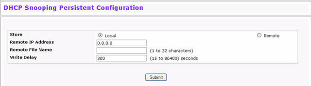
DHCP Snooping Persistent Configuration
Field |
Description |
|---|---|
Store Locally |
|
Remote IP Address |
Enter the Remote IP address on which the snooping database will be stored when the Remote check box is selected. |
Remote File Name |
Enter the Remote filename to store the database when the Remote check box is selected. |
Write Delay |
Enter the maximum write time to write the database into local or remote. The write delay range is 15 to 86400 seconds. |
Click Submit to apply the new configuration and cause the change to take effect. These changes will not be retained across a power cycle unless a Save configuration is performed.
The DHCP Snooping Statistics page displays DHCP snooping interface statistics. To access the DHCP Snooping Statistics page, click Switching > DHCP Snooping > Statistics in the navigation menu. The following figure shows the page when DHCP snooping is configured on at least one interface.
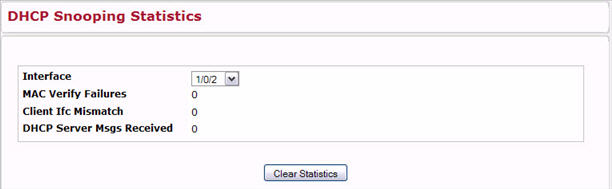
DHCP Snooping Statistics
Field |
Description |
|---|---|
Interface |
Select the untrusted and snooping-enabled interface for which statistics are to be displayed. |
MAC Verify Failures |
The number of packets that were dropped by DHCP snooping because there is no matching DHCP snooping binding entry found. |
Client Ifc Mismatch |
The number of DHCP messages that are dropped based on the source MAC address and client hardware address verification. |
DHCP Server Msgs Received |
The number of server messages that are dropped on an untrusted port. |
Click Clear Stats to clear all interface statistics.
When a DHCP client and server are in the same IP subnet, they can directly connect to exchange IP address requests and replies. However, having a DHCP server on each subnet can be expensive in and is often impractical. Alternatively, network infrastructure devices can be used to relay packets between a DHCP client and server on different subnets. Such a device, a Layer 3 Relay agent, is generally a router that has IP interfaces on both the client and server subnets and can route between them. However, in Layer 2 switched networks, there may be one or more infrastructure devices between the client and the L3 Relay agent/DHCP server. In this instance, some of the client device information required by the L3 Relay agent may not be visible to it. In this case, an L2 Relay agent can be used to add the information that the L3 Relay Agent and DHCP server need to perform their roles in address and configuration and assignment.
Before it relays DHCP requests from clients, the switch can add a Circuit ID and a Remote ID. These provide information about the circuit and port number connected to the client. This information is added as suboptions in the DHCP Option 82 packets. The switch removes this option from packets that it relays from L3 Relay agents/DHCP servers to clients.
These sub-options may be used by the DHCP server to affect how it treats the client, and also may be used by the relay agent to limit broadcast replies to the specific circuit or attachment point of the client.
DHCP L2 Relay Global Configuration
Use this page to enable or disable the switch to act as a DHCP L2 relay agent. This functionality must also be enabled on each port you want this service to operate on. The switch can also be configured to relay requests only when the VLAN of the requesting client corresponds to a service provider’s VLAN ID that has been enabled with the L2 DHCP relay functionality.
To access this page, click Switching > DHCP Snooping > DHCP L2 Relay > Global Configuration.
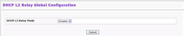
If you enable or disable this feature, click Submit to apply the changes to system.
DHCP L2 Relay Interface Configuration
Use this page to enable L2 DHCP relay on individual ports.
NOTE: L2 DHCP relay must also be enabled globally on the switch.
To access this page, click Switching > DHCP Snooping > DHCP L2 Relay > Interface Configuration.
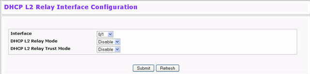
DHCP L2 Relay Interface Configuration
Field |
Description |
|---|---|
Interface |
Select the slot/port to configure this feature on. |
DHCP L2 Relay Mode |
Enable or disable L2 Relay mode on the selected interface. |
DHCP L2 Relay Trust Mode |
Enable or disable L2 Relay Trust Mode on the selected interface. Trusted interfaces usually connect to other agents or servers participating in the DHCP interaction. When enabled in Trust Mode, the interface always expects to receive DHCP packets that include Option 82 information. If Option 82 information is not included, these packets are discarded. Untrusted interfaces are generally connected to clients. DHCP packets arriving on an untrusted interface are never expected to carry Option 82 and are discarded if they do. |
If you change any settings on this page, click Submit to apply the changes to system.
DHCP L2 Relay VLAN Configuration
You can enable L2 DHCP relay on a particular VLAN. The VLAN is identified by a service VLAN ID (S-VID), which a service provider uses to identify a customer’s traffic while traversing the provider network to multiple remote sites. The switch uses the VLAN membership of the switch port client (the customer VLAN ID, or C-VID) to perform a lookup a corresponding S-VID.
NOTE: You can use the Dot1ad feature to configure C-VID and S-VID correspondences.
If the S-VID is enabled for DHCP L2 Relay, the packet can be forwarded. If the C-VID does not correspond to an S-VID that is enabled for DHCP L2 relay, the switch will not relay the DHCP request packet. To access this page, click Switching > DHCP Snooping > DHCP L2 Relay > VLAN Configuration.
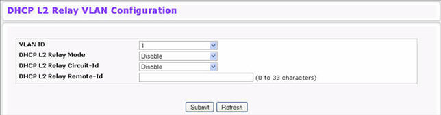
DHCP L2 Relay VLAN Configuration
Field |
Description |
|---|---|
VLAN ID |
Select a VLAN ID from the list for configuration. This is an S-VID (as indicated by the service provider) that identifies a VLAN that is authorized to relay DHCP packets through the provider network. |
DHCP L2 Relay Mode |
Enable or disable the selected VLAN for DHCP L2 relay services. |
DHCP L2 Relay Circuit-Id |
When enabled, if a client sends a DHCP request to the switch and the client is in a VLAN that corresponds to the selected S-VID, the switch adds the client’s interface number to the Circuit ID sub-option of Option 82 in the DHCP request packet. This enables the switch to reduce the broadcast domain to which the server replies are switched when the broadcast bit is set for DHCP packets. When this bit is set, the server is required to echo the Option-82 in replies. Since the circuit-id field contains the client interface number, the L2 relay agent can forward the response to the requesting interface only, rather to all ports in the VLAN). |
DHCP L2 Relay Remote-Id |
When a string is entered here, if a client sends a DHCP request to the switch and the client is in a VLAN that corresponds to the selected SVID, the switch adds the string to the Remote-ID sub-option of Option 82 in the DHCP request packet. This sub-option can be used by the server for parameter assignment. The content of this option is vendor-specific. |
If you change any settings on this page, click Submit to apply the changes to system.
DHCP L2 Relay Interface Statistics
Use this page to display statistics on L2 DHCP Relay requests received on a selected port. To access this page, click Switching > DHCP Snooping > DHCP L2 Relay > Interface Statistics.
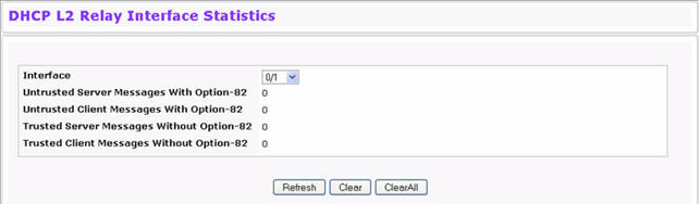
DHCP L2 Relay Interface Statistics
Field |
Description |
|---|---|
Interface |
Select the interface with the information to view. |
Untrusted Server Msgs With Option—82 |
If the selected interface is configured in untrusted mode, this field shows the number of messages received on the interface from a DHCP server that contained Option 82 data.These messages are dropped. |
Untrusted Client Msgs With Option—82 |
If the selected interface is configured in untrusted mode, this field shows the number of messages received on the interface from a DHCP client that contained Option 82 data.These messages are dropped. |
Trusted Server Msgs Without Option—82 |
If the selected interface is configured in trusted mode, this field shows the number of messages received on the interface from a DHCP server that did not contain Option 82 data. These messages are dropped. |
Trusted Client Msgs Without Option—82 |
If the selected interface is configured in trusted mode, this field shows the number of messages received on the interface from a DHCP client that did not contain Option 82 data. These messages are dropped. |
Command Buttons
The following command buttons are available on the page:
DHCP L2 Relay Subscription Configuration
Use this page to display and set the configuration on L2 DHCP Relay Subscription. To access this page, click Switching > DHCP Snooping > DHCP L2 Relay > Subscription Configuration.
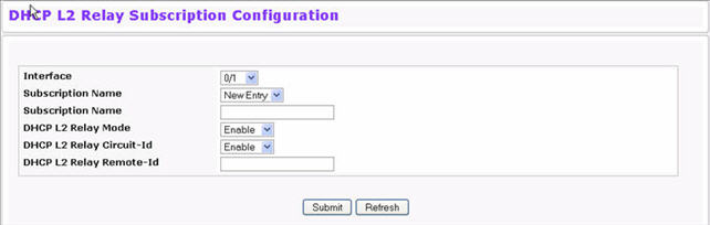
DHCP L2 Relay Subscription Configuration
Field |
Description |
|---|---|
Interface |
Select the slot/port to configure this feature on. |
Subscription Name |
Select the host name from the list or select New Entry to add a new. |
Subscription Name |
Enter the host name. |
DHCP L2 Relay Mode |
Enable or disable L2 Relay mode on the selected interface. |
DHCP L2 Relay Circuit-Id |
Enable or disable Circuit ID Option mode. If set to ‘enable’, Relay agents options will be added to requests before they are forwarded to the server and removed from the replies before they are forwarded to the clients. |
DHCP L2 Relay Remote-Id |
Enter the L2 Relay remote ID. When DHCP L2 Relay Circuit‐Id is enabled, the supplied string is used for the Remote ID in DHCP option. |
The following command buttons are available on the page:
DHCP L2 Relay Subscription Summary
Use this page to display summary on L2 DHCP Relay Subscription. To access this page, click Switching > DHCP Snooping > DHCP L2 Relay > Subscription Summary.
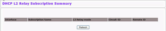
DHCP L2 Relay Subscription Summary
Field |
Description |
|---|---|
Interface |
Displays the interface. |
Subscription Name |
It displays the host name. |
L2 Relay Mode |
Displays the L2 Relay mode on the selected interface. |
Circuit-Id |
Displays the L2 Relay Circuit ID. |
Remote-Id |
Displays the L2 Relay remote ID. |
Click Refresh to redisplay the page with the latest information from the switch.
IP Source Guard (IPSG) is a security feature that filters IP packets based on source ID. The source ID may be either the source IP address or a {source IP address, source MAC address} pair. You can configure:
The DHCP snooping bindings database and static IPSG entries identify authorized source IDs. IPSG is enabled on physical and LAG ports. IPSG is disabled by default.
If you enable IPSG on a port where DHCP snooping is disabled or where DHCP snooping is enabled but the port is trusted, all IP traffic received on that port is dropped depending on the admin-configured IPSG entries. IPSG cannot be enabled on a port-based routing interface.
IPSG Interface Configuration
To access the IP Source Guard Interface Configuration page, click Switching > IP Source Guard > IPSG Interface Configuration in the navigation menu.
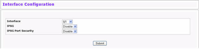
IPSG Interface Configuration
Field |
Description |
|---|---|
Interface |
Select the interface for which data is to be displayed or configured. |
IPSG |
Enables or disables validation of the Sender IP Address on this interface. If IPSG is Enabled, packets will not be forwarded if the Sender IP Address is not in the DHCP Snooping Binding database. The default is Disable. |
IPSG Port Security |
Enables or disables the IPSG Port Security on the selected interface. If IPSG Port Security is Enabled, the packets will not be forwarded if the sender MAC Address is not in the FDB table and if it is not in the DHCP snooping binding database. To enforce filtering based on the MAC address, other required configurations are:
IPSG port-security cannot be enabled if IPSG is disabled. The default is Disable. |
Click Submit to apply the new configuration and cause the change to take effect. These changes will not be retained across a power cycle unless a Save configuration is performed.
IPSG Binding Configuration
To access the IPSG Binding Configuration page, click Switching > IP Source Guard > IPSG Binding Configuration in the navigation menu.
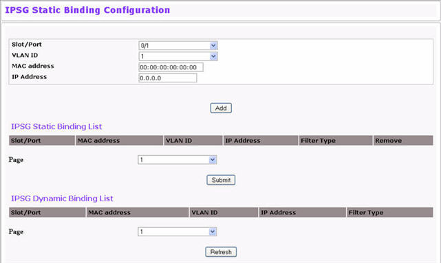
IPSG Binding Configuration
Field |
Description |
|---|---|
Unit/Slot/Port |
Select the interface to add a binding into the IPSG database. |
VLAN ID |
Select the VLAN from the list for the binding rule. |
MAC Address |
Specify the MAC address for the binding. |
IP Address |
Specify a valid IP address for the binding rule. |
The IPSG Static Binding List lists all the IPSG static binding entries page by page.
IPSG Static Binding List
Field |
Description |
|---|---|
Unit/Slot/Port |
Displays the interface. |
MAC Address |
Displays the MAC address. |
VLAN ID |
Displays the VLAN ID. |
IP Address |
Displays the IP address. |
Filter Type |
Displays the filter type. |
Remove |
Select this to remove a particular binding entry. |
Page |
Lists the number of pages the IPSG static binding entries occupy. Select the page number to display the particular page entries. |
The IPSG Static Binding List lists all the IPSG static binding entries page by page.
IPSG Dynamic Binding List
Field |
Description |
|---|---|
Unit/Slot/Port |
Displays the interface. |
MAC Address |
Displays the MAC address. |
VLAN ID |
Displays the VLAN ID. |
IP Address |
Displays the IP address. |
Filter Type |
Displays the IPSG filtering type. |
Page |
Lists the number of pages the IPSG dynamic binding entries occupy. Select the page number to display the particular page entries. |