![]()
![]()
![]()
![]()
|
|
|
|
|
Port-channels, which are also known as link aggregation groups (LAGs), allow you to combine multiple full-duplex Ethernet links into a single logical link. Network devices treat the aggregation as if it were a single link, which increases fault tolerance and provides load sharing. You assign the port-channel (LAG) VLAN membership after you create a port-channel. The port channel by default becomes a member of the management VLAN.
A port-channel (LAG) interface can be either static or dynamic, but not both. All members of a port channel must participate in the same protocols. A static port-channel interface does not require a partner system to be able to aggregate its member ports.
NOTE: If you configure the maximum number of dynamic port-channels (LAGs) that your platform supports, additional port-channels that you configure are automatically static.
Static LAGs are supported. When a port is added to a LAG as a static member, it neither transmits nor receives LACPDUs.
Use the Port Channel Configuration page to group one or more full duplex Ethernet links to be aggregated together to form a port-channel, which is also known as a link aggregation group (LAG). The switch treats the port-channel as if it were a single link. To access the Port Channel Configuration page, click Switching > Port Channel > Configuration in the navigation menu.
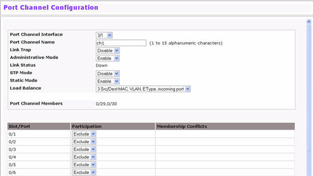
Port Channel Configuration Fields
Field |
Description |
|---|---|
Port Channel Interface |
Select the port channel to configure. The port channel follows a Slot/Port (or Unit/Slot/Port for stacking platforms) interface naming convention, where the slot is 3. |
Port Channel Name |
Enter the name you want assigned to the Port Channel. You may enter any string of up to 15 alphanumeric characters. You must specify a valid name in order to create the Port Channel. |
Link Trap |
Specify whether you want to have a trap sent when link status changes. The factory default is enable, which will cause the trap to be sent. |
Administrative Mode |
Select enable or disable from the pulldown menu. When the Port Channel is disabled no traffic will flow and LACPDUs will be dropped, but the links that form the Port Channel will not be released. The factory default is enable. |
Link Status |
Indicates whether the link is Up or Down. |
STP Mode |
Select the Spanning Tree Protocol (STP) Administrative Mode associated with the Port Channel:
|
Static Mode |
Select enable or disable from the pulldown menu. The factory default is Disable.
|
Local Preference Mode |
This field is available only on systems that support stacking. When this option is enabled, the LAG-destined unicast traffic egresses only out of members of the LAG interface on the local unit. This feature makes sure that the LAG-destined unicast traffic does not cross the external stack link when the LAG has members on the local unit. |
Load Balance |
Select the hashing algorithm used to distribute the traffic load among available physical ports in the LAG. The range of possible values may vary with the type of switch. The possible values are:
|
Port Channel Members |
After you create one or more port channel, this field lists the members of the Port Channel. If there are no port channels on the system, this field is not present. |
Unit/Slot/Port |
This column lists the physical ports available on the system. |
Participation |
Select each port’s membership status for the Port Channel you are configuring. There can be a maximum of 8 ports assigned to a Port Channel.
|
Membership Conflicts |
Shows ports that are already members of other Port Channels. A port may only be a member of one Port Channel at a time. If the entry is blank, the port is not currently a member of any Port Channel. |
Use the Port Channel Status page to group one or more full duplex Ethernet links to be aggregated together to form a port-channel, which is also known as a link aggregation group (LAG). The switch can treat the port-channel as if it were a single link. To access the Port Channel Status page, click Switching > Port Channel > Status in the navigation menu.
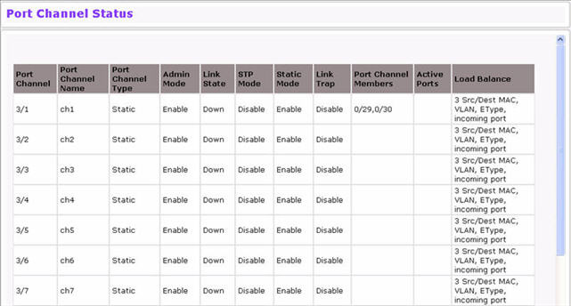
Port Channel Status Fields
Field |
Description |
|---|---|
Port Channel |
Identifies the port channel with the Slot/Port (or Unit/Slot/Port for stacking platforms) interface naming convention. |
Port Channel Name |
Identifies the user-configured text name of the port channel. |
Port Channel Type |
The type of this Port Channel, which is one of the following:
|
Admin Mode |
Select enable or disable from the pulldown menu. When the Port Channel is disabled no traffic will flow and LACPDUs will be dropped, but the links that form the Port Channel will not be released. The factory default is enable. |
Link State |
Indicates whether the link is Up or Down. |
STP Mode |
Shows whether the Spanning Tree Protocol (STP) Administrative Mode is enabled or disabled on the port channel. |
Link Trap |
Shows whether to send traps when link status changes. If the status is Enabled, traps are sent. |
Static Mode |
Shows whether static mode is enabled for this port channel. |
Port Channel Members |
Lists the ports that are members of the Port Channel, in Slot/Port notation (Unit/Slot/Port for stackable systems). There can be a maximum of 8 ports assigned to a Port Channel. |
Active Ports |
Lists the ports that are actively participating members of this Port Channel, in Slot/Port notation (Unit/Slot/Port for stackable systems). |
Load Balance |
Shows the hashing algorithm used to distribute the traffic load among available physical ports in the LAG. The range of possible values may vary with the type of switch. The possible values are:
|