![]()
![]()
![]()
![]()
|
|
|
|
|
The Spanning Tree Protocol (STP) provides a tree topology for any arrangement of bridges. STP also provides one path between end stations on a network, eliminating loops. Spanning tree versions supported include Common STP, Multiple STP, and Rapid STP.
Classic STP provides a single path between end stations, avoiding and eliminating loops.
Multiple Spanning Tree Protocol (MSTP) supports multiple instances of Spanning Tree to efficiently channel VLAN traffic over different interfaces. Each instance of the Spanning Tree behaves in the manner specified in IEEE 802.1w, Rapid Spanning Tree (RSTP), with slight modifications in the working but not the end effect (chief among the effects, is the rapid transitioning of the port to ‘Forwarding’). The difference between the RSTP and the traditional STP (IEEE 802.1D) is the ability to configure and recognize full duplex connectivity and ports which are connected to end stations, resulting in rapid transitioning of the port to ‘Forwarding’ state and the suppression of Topology Change Notification. These features are represented by the parameters ‘pointtopoint’ and ‘edgeport’. MSTP is compatible to both RSTP and STP. It behaves appropriately to STP and RSTP bridges. A MSTP bridge can be configured to behave entirely as a RSTP bridge or a STP bridge.
NOTE: For two bridges to be in the same region, the force version should be 802.1S and their configuration name, digest key, and revision level should match.
The Spanning Tree Switch Configuration/Status page contains fields for enabling STP on the switch. To display the Spanning Tree Switch Configuration/Status page, click Switching > Spanning Tree > Switch Configuration/Status in the navigation menu.
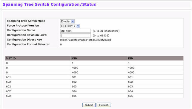
Spanning Tree Switch Configuration/Status Fields
Field |
Description |
|---|---|
Spanning Tree Admin Mode |
Enables or disables STP on the switch. |
Force Protocol Version |
Specifies the Force Protocol Version parameter for the switch:
|
Configuration Name |
Name used to identify the configuration currently being used. It may be up to 32 alphanumeric characters. |
Configuration Revision Level |
Number used to identify the configuration currently being used. The values allowed are between 0 and 65535. The default value is 0. |
Configuration Digest Key |
Number used to identify the configuration currently being used. The digest key is generated based on the association of VLANs to different instances. To ensure the digest key is same on two different switches, the mapping of VLAN-to-instance must be the same. |
Configuration Format Selector |
Identifies the format selector. A value of 0 indicates the use of fields as defined in IEEE 802.1Q™-2003. |
MST ID |
Table consisting of the MST instances (including the CST) and the corresponding VLAN IDs associated with each of them. |
VID |
This table consists of the VLAN identifier (VID) and the corresponding filtering identifier (FID) associated with each VID. |
FID |
Table consisting of the FIDs and the corresponding VLAN IDs associated with each of them. |
Use the Spanning Tree CST Configuration/Status page to configure Common Spanning Tree (CST) and Internal Spanning Tree on the switch.
To display the Spanning Tree CST Configuration/Status page, click Switching > Spanning Tree > CST Configuration/Status in the navigation menu.
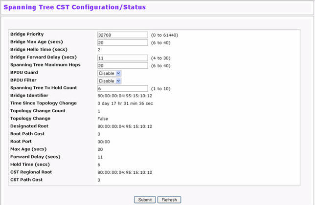
Spanning Tree CST Configuration/Status Fields
Field |
Description |
|---|---|
Bridge Priority |
Specifies the bridge priority value. When switches or bridges are running STP, each is assigned a priority. After exchanging BPDUs, the switch with the lowest priority value becomes the root bridge. The bridge priority is a multiple of 4096. If you specify a priority that is not a multiple of 4096, the priority is automatically set to the next lowest priority that is a multiple of 4096. |
Bridge Max Age (secs) |
Specifies the switch maximum age time, which indicates the amount of time in seconds a bridge waits before implementing a topological change. The valid range is 6-40, and the value must be less than or equal to (2 * Bridge Forward Delay) – 1 and greater than or equal to 2 * (Bridge Hello Time +1). The default value is 20. |
Bridge Hello Time (secs) |
Specifies the switch Hello time, which indicates the amount of time in seconds a root bridge waits between configuration messages. The valid range is 1-10, and the default value is 2. The value must be less than or equal to (Bridge Max Age / 2) – 1. The default hello time value is 2. |
Bridge Forward Delay (secs) |
Specifies the switch forward delay time, which indicates the amount of time in seconds a bridge remains in a listening and learning state before forwarding packets. The value must be greater or equal to (Bridge Max Age / 2) + 1. The time range is from 4 seconds to 30 seconds. The default value is 15. |
Spanning Tree Maximum Hops |
Specifies the maximum number of bridge hops the information for a particular CST instance can travel before being discarded. |
BPDU Guard |
Enable or disable the BPDU Guard.The switches behind the edge ports that have BPDU guard enabled will not be able to influence the overall STP topology. Using the BPDU Guard feature can help enforce the STP domain borders and keep the active topology be consistent and predictable. |
BPUD Filter |
Enable or disable the BPDU Filter. When BPDU filtering is enabled, the port drops the BPDUs received. |
Spanning Tree Tx Hold Count |
Configure the maximum number of BPDUs the bridge is allowed to send within the hello time window.The default value is 6. |
Bridge Identifier |
The bridge identifier for the CST. It is made up using the bridge priority and the base MAC address of the bridge. |
Time Since Topology Change |
Displays the total amount of time since the last topographic change. The time is displayed in hour/minute/second format. |
Topology Changes Counts |
Displays the total amount of STP state changes that have occurred. |
Topology Change |
Indicates whether a topology change is in progress on any port assigned to the CST. The possible values are True or False. |
Designated Root |
Displays the bridge identifier of the root bridge, which is made up from the bridge priority and the base MAC address of the bridge. |
Root Path Cost |
Displays the cost of the path from this bridge to the designated root. |
Root Port |
Indicates the root port of the selected instance. |
Max Age |
Shows the path Cost to the Designated Root for the CST. |
Forward Delay |
Shows the derived value of the Root Port Bridge Forward Delay parameter. |
Hold Time |
Indicates the minimum time between transmission of Configuration BPDUs. |
CST Regional Root |
Shows the priority and base MAC address of the CST Regional Root. |
CST Path Cost |
Shows the path Cost to the CST tree Regional Root. |
Use the Spanning Tree MST Configuration/Status page to configure Multiple Spanning Tree (MST) on the switch. To display the Spanning Tree MST Configuration/Status page, click Switching > Spanning Tree > MST Configuration/Status in the navigation menu.
If no MST instances exist, or if you select Create from the MST field, the MST Configuration/Status page looks like the screen in Figure below.
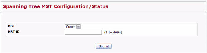
Figure below shows an example of the page with an MST instance configured.
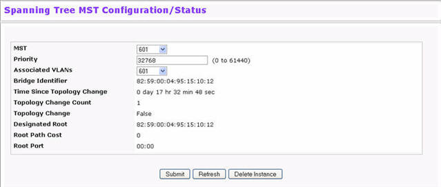
Spanning Tree MST Configuration/Status
Field |
Description |
|---|---|
MST |
Use the drop-down menu to create and configure a new MST or select an existing MST to display or configure. |
MST ID |
This is only visible when Create is selected from the MST field drop-down menu. The ID of the MST being created. Valid values for this are between 1 and 4094. |
Priority |
Specifies the bridge priority value for the MST. When switches or bridges are running STP, each is assigned a priority. After exchanging BPDUs, the switch with the lowest priority value becomes the root bridge. The bridge priority is a multiple of 4096. If you specify a priority that is not a multiple of 4096, the priority is automatically set to the next lowest priority that is a multiple of 4096. |
Associated VLANs |
This field gives a list of VLANs associated to the MST instance. Non-configured VLANs can be added to or deleted from the MST instance by selecting Add/Delete option and entering the VLAN ID in the VLAN ID-Individual/Range text-box. |
VLAN ID-Individual/Range |
This field is visible only if Create or Delete is selected from the Associated VLANs menu. Specify the VLAN ID or range of VLAN IDs to add to or delete from the MST instance. |
Bridge Identifier |
The bridge identifier for the selected MST instance. It is made up using the bridge priority and the base MAC address of the bridge. |
Time Since Topology Change |
Displays the total amount of time since the last topographic change. The time is displayed in hour/minute/second format. |
Topology Changes Counts |
Displays the total number of MST state changes that have occurred. |
Topology Change |
Indicates whether a topology change is in progress on any port assigned to the CST. The possible values are True or False. |
Designated Root |
Displays the bridge identifier of the root bridge, which is made up from the bridge priority and the base MAC address of the bridge. |
Root Path Cost |
Displays the path cost to the Designated Root for this MST instance. |
Root Port |
Indicates the port to access the Designated Root for this MST instance. |
Use the Spanning Tree CST Port Configuration/Status page to configure Common Spanning Tree (CST) and Internal Spanning Tree on a specific port on the switch.
To display the Spanning Tree CST Port Configuration/Status page, click Switching > Spanning Tree > CST Port Configuration/Status in the navigation menu.
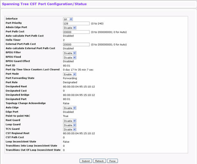
Spanning Tree CST Port Configuration/Status Fields
Field |
Description |
|---|---|
Interface |
Select a physical or port channel interface to configure. The port is associated with the VLAN(s) associated with the CST. |
Port Priority |
The priority for a particular port within the CST. The port priority is set in multiples of 16. If you specify a value that is not a multiple of 16, the priority is automatically set to the next lowest priority that is a multiple of 16. |
Admin Edge Port |
Determines whether the specified port is an Edge Port within the CIST. It takes a value of TRUE or FALSE, where the default value is FALSE. |
Port Path Cost |
Set the Path Cost to a new value for the specified port in the common and internal spanning tree. It takes a value in the range of 1 to 200000000. |
Auto-calculate Port Path Cost |
Displays whether the path cost is automatically calculated (Enabled) or not (Disabled). Path cost is calculated based on the link speed of the port if the configured value for Port Path Cost is zero. |
Hello Timer |
Specifies the switch Hello time, which indicates the amount of time in seconds a port waits between configuration messages. The valid range is 1-10, and the default value is 2. The value must be less than or equal to (Bridge Max Age / 2) – 1. The default hello time value is 2. |
External Port Path Cost |
Set the External Path Cost to a new value for the specified port in the spanning tree. It takes a value in the range of 1 to 200000000. |
Auto-calculate External Port Path Cost |
Displays whether the external path cost is automatically calculated (Enabled) or not (Disabled). External Path cost will be calculated based on the link speed of the port if the configured value for External Port Path Cost is zero. |
BPDU Filter |
Enable or disable the BPDU Filter, which filters the BPDU traffic on this port when STP is enabled on this port. |
BPDU Flood |
Enable or disable the BPDU Flood, which floods the BPDU traffic arriving on this port when STP is disabled on this port. |
BPDU Guard Effect |
If BPDU Guard is enabled for the switch and the edge port receives a BPDU, the port will be disabled and the status of this field is Enabled. |
Port ID |
The port identifier for the specified port within the CST. It is made up from the port priority and the interface number of the port. |
Port Up Time Since Counters Last Cleared |
Time since the counters were last cleared, displayed in Days, Hours, Minutes, and Seconds. |
Port Mode |
Spanning Tree Protocol Administrative Mode associated with the port or port channel. The possible values are Enable or Disable. |
Port Forwarding State |
Indicates the current STP state of a port. If enabled, the port state determines what forwarding action is taken on traffic. Possible port states are:
|
Port Role |
Each MST Bridge Port that is enabled is assigned a Port Role for each spanning tree. The port role will be one of the following values: Root Port, Designated Port, Alternate Port, Backup Port, Master Port or Disabled Port. |
Designated Root |
Root Bridge for the CST. It is made up using the bridge priority and the base MAC address of the bridge. |
Designated Cost |
Displays cost of the port participating in the STP topology. Ports with a lower cost are less likely to be blocked if STP detects loops. |
Designated Bridge |
Bridge Identifier of the bridge with the Designated Port. It is made up using the bridge priority and the base MAC address of the bridge. |
Designated Port |
Port Identifier on the Designated Bridge that offers the lowest cost to the LAN. It is made up from the port priority and the interface number of the port. |
Topology Change Acknowledge |
Identifies whether the next BPDU to be transmitted for this port would have the topology change acknowledgment flag set. It is either "True" or "False". |
Auto Edge |
Configuring the auto edge mode of a port allows the port to become an edge port if it does not see BPDUs for some duration. The possible values are Enable or Disable. |
Edge Port |
Indicates whether the port is enabled as an edge port. |
Point-to-point MAC |
Derived value of the point-to-point status. |
Root Guard |
Configuring the root guard mode sets a port to discard any superior information received by the port and thus protect against root of the device from changing. The port gets put into discarding state and does not forward any packets.The possible values are Enable or Disable. |
Loop Guard |
Configuring the loop guard mode prevents a port from erroneously transitioning from blocking state to forwarding when the port stops receiving BPDUs. The port is marked as being in loop-inconsistent state. In this state, the port does not forward packets. The possible values are Enable or Disable. |
TCN Guard |
Configuring the TCN guard for a port restricts the port from propagating any topology change information received through that port.The possible values are Enable or Disable. |
CST Regional Root |
Shows the priority and base MAC address of the CST Regional Root. |
CST Path Cost |
Shows the path Cost to the CST tree Regional Root. |
Loop Inconsistent State |
Identifies whether the port is currently in a loop inconsistent state. If the port is in a loop inconsistent state, it does not forward packets. |
Transitions Into Loop Inconsistent State |
Shows the number of times this interface has moved into a loop inconsistent state. |
Transitions Out Of Loop Inconsistent State |
Shows the number of times this interface has gotten out of a loop inconsistent state. |
Use the Spanning Tree MST Port Configuration/Status page to configure Multiple Spanning Tree (MST) on a specific port on the switch.
To display the Spanning Tree MST Port Configuration/Status page, click Switching > Spanning Tree > MST Port Configuration/Status in the navigation menu.
NOTE: If no MST instances have been configured on the switch, the page displays a “No MSTs Available” message and does not display the fields shown in Figure below.
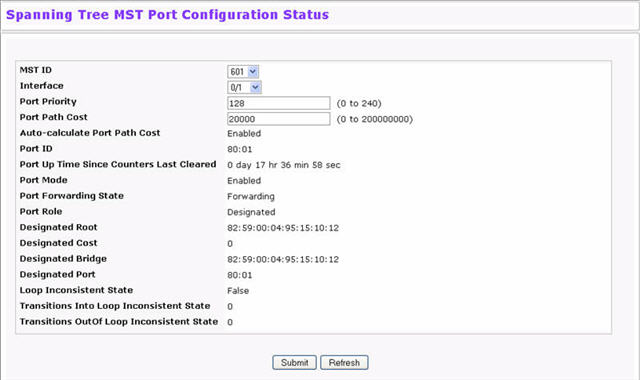
Spanning Tree MST Port Configuration/Status Fields
Field |
Description |
|---|---|
MST ID |
Select an existing MST instance from drop-down list to display or configure its values. |
Interface |
Select a physical or port channel interface to configure. The port is associated with the VLAN(s) associated with the MST. |
Port Priority |
The priority for a particular port within the MST. The port priority is set in multiples of 16. If you specify a value that is not a multiple of 16, the priority is set to the priority is automatically set to the next lowest priority that is a multiple of 16. |
Port Path Cost |
Set the Path Cost to a new value for the specified port in the selected MST instance. It takes a value in the range of 1 to 200000000. |
Auto-calculate Port Path Cost |
Displays whether the path cost is automatically calculated (Enabled) or not (Disabled). Path cost is calculated based on the link speed of the port if the configured value for Port Path Cost is zero. |
Port ID |
The port identifier for the specified port within the CST. It is made up from the port priority and the interface number of the port. |
Port Up Time Since Counters Last Cleared |
Time since the counters were last cleared, displayed in Days, Hours, Minutes, and Seconds. |
Port Mode |
Shows whether STP is enabled on the port. To enable STP on a port, use the System > Port > Configuration page. |
Port Forwarding State |
Indicates the current STP state of a port. If enabled, the port state determines what forwarding action is taken on traffic. Possible port states are:
|
Port Role |
Each MST Bridge Port that is enabled is assigned a Port Role for each spanning tree. The port role will be one of the following values: Root Port, Designated Port, Alternate Port, Backup Port, Master Port or Disabled Port. |
Designated Root |
Root Bridge for the selected MST instance. It is made up using the bridge priority and the base MAC address of the bridge. |
Designated Cost |
Displays cost of the port participating in the STP topology. Ports with a lower cost are less likely to be blocked if STP detects loops. |
Designated Bridge |
Bridge Identifier of the bridge with the Designated Port. It is made up using the bridge priority and the base MAC address of the bridge. |
Designated Port |
Port Identifier on the Designated Bridge that offers the lowest cost to the LAN. It is made up from the port priority and the interface number of the port. |
Loop Inconsistent State |
This parameter identifies whether the port is in a loop inconsistent state in the specified MST instance. If the port is in a loop inconsistent state, it does not forward packets. |
Transitions Into Loop Inconsistent State |
Shows the number of times this interface has gone into a loop inconsistent state. |
Transitions Out Of Loop Inconsistent State |
Shows the number of times this interface has gotten out of a loop inconsistent state. |
Use the Spanning Tree Statistics page to view information about the number and type of bridge protocol data units (BPDUs) transmitted and received on each port.
To display the Spanning Tree Statistics page, click Switching > Spanning Tree > Statistics in the navigation menu.
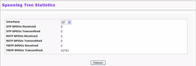
Spanning Tree Statistics Fields
Field |
Description |
|---|---|
Interface |
Select a physical or port channel interface to view its statistics. |
STP BPDUs Received |
Number of STP BPDUs received at the selected port. |
STP BPDUs Transmitted |
Number of STP BPDUs transmitted from the selected port. |
RSTP BPDUs Received |
Number of RSTP BPDUs received at the selected port. |
RSTP BPDUs Transmitted |
Number of RSTP BPDUs transmitted from the selected port. |
MSTP BPDUs Received |
Number of MSTP BPDUs received at the selected port. |
MSTP BPDUs Transmitted |
Number of MSTP BPDUs transmitted from the selected port. |
Click Refresh to update the screen with most recent data.