![]()
![]()
![]()
![]()
|
|
|
|
|
Like 802.1AS, Multiple Registration Protocol (MRP) is an Audio Video Bridging (AVB) feature that is available on some TejNOS-EN platforms. MVR is a base registration protocol that enables devices running an MRP application to register attributes to other devices in a network. MRP provides an application to register attributes such as bandwidth requirement for a given AV stream and MAC address information. It is used by various applications to propagate the registration. TejNOS-EN switches support the following MRP applications:
MMRP allows for the propagation MAC address information in the network, and allows for the registration and deregistration of both individual MAC address information and group MAC address membership. End stations may request to join or leave a multicast group, or to register an individual MAC address with a specific VLAN. MAC address entries can be dynamically registered and deregistered if MMRP is administratively enabled on the switch.
MSRP reserves necessary resources in the network to facilitate time sensitive traffic to flow end to end. In a typical network, there are multiple Talkers (those who transmit streams) and multiple Listeners (those who receive streams from one or many Talkers). Each flow has specific bandwidth, frame rate, and time sync requirements. With the use of MSRP these resources are guaranteed through all intermediate devices that are between any talker and listener.
MVRP registers VLANs in the network, enabling automatic VLAN configuration on the switch. In a typical network, VLAN tagging is common. Many nodes require ingress traffic to be tagged with specific VLAN ID, and other nodes require egress traffic to be transmitted with a specific VLAN ID. With the use of MVRP on both ingress and egress, no manual VLAN configuration is required to pass tagged traffic through the network.
NOTE: MRP framework must be available and enabled in all intermediate devices to ensure that the propagation of the attributes occurs throughout the network.
With MRP, network attributes are declared, registered, withdrawn, and removed completely dynamically without any user intervention. This dynamic nature is especially useful in networks where:
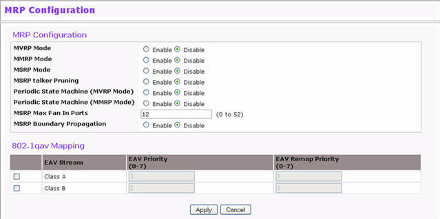
Use the MRP Configuration page to configure global MRP settings for the switch. To access the basic MRP Configuration page click Switching > MRP > MRP Configuration.
NOTE: The fields available on the MRP Configuration page vary based on the platform and its supported features.
MRP Configuration Fields
Field |
Description |
|---|---|
MVRP Mode |
Enable or disable MVRP globally on the switch. MVRP provides an application to register VLAN information. |
MMRP Mode |
Enable or disable MMRP globally on the switch. MMRP provides an application to register MAC address information. |
MSRP Mode |
Enable or disable MSRP globally on the switch. MSRP provides an application to register bandwidth requirement for a given AV stream. |
MSRP talker pruning |
Enable or disable MSRP talker Pruning. The MSRP talker is the source of an AV stream. |
Periodic State Machine (MVRP Mode) |
Enable or disable the MRP Periodic State Machine for MVRP on device. Default mode is Disable. |
Periodic State Machine (MMRP Mode) |
Enable or disable the MRP Periodic State Machine for MMRP on device. Default mode is Disable. |
MSRP Max Fan In Ports |
Specify the maximum number of the ports where MSRP registrations are allowed. |
MSRP Boundary Propagation |
Enable or disable MSRP Boundary Propagation on the switch. |
EAV Stream |
Configure the 802.1Qav mapping for the Class A and/or Class B EAV streams. Class A streams have a higher transmission priority than Class B traffic. |
EAV Priority field |
Specify the priority for each EAV stream class. The range is 0-7. |
EAV Remap Priority |
Specify the remap priority for non‐EAV traffic. The range is 0-7. |
Use the MRP Port Settings page to configure the per-port MRP mode and timer settings. The timers control when and how often various messages are transmitted on each interface.
To access the Port Settings page click Switching > MRP > Port Settings in the navigation menu. In the following image, the MMRP mode on ports g4 and g5 is being enabled.
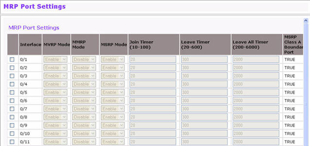
To configure one or more ports or LAGs, select the check box next to each port or LAG to configure. You can select multiple ports to apply the same settings to the selected interfaces.
MRP Port Configuration Fields
Field |
Description |
|---|---|
Interface |
Identifies the interface associated with the rest of the information in the row. |
MVRP Mode |
Enable or disable MVRP on the interface. |
MMRP Mode |
Enable or disable MMRP on the interface. |
MSRP Mode |
Enable or disable MSRP on the interface. |
Join Timer |
Specify the value, in centiseconds, of the MRP Join Timer. The range is 10 to 100 centiseconds, and the default value is 20. |
Leave Timer |
Specify the value, in centiseconds, of the MRP Leave Timer. The range is 10 to 600 centiseconds, and the default value is 120. |
Leave All Timer |
Specify the value, in centiseconds, of the MRP LeaveAll Timer. The range is 200 to 6000 centiseconds, and the default value is 2000. |
MSRP Class A Boundary Port |
Shows whether the interface is a Class A boundary port. |
MSRP Class B Boundary Port |
Shows whether the interface is a Class B boundary port. |
MSRP SR class PVID |
Specify the default VLAN ID to be used for MSRP stream traffic. |
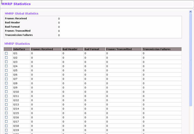
The MMRP Statistics page displays information regarding the MMRP frames transmitted and received by the switch and by each interface. To access the MMRP Statistics page click the Switching tab, then click MRP > Advanced > MMRP Statistics.
MMRP Statistics Fields
Field |
Description |
|
|---|---|---|
Global MMRP Statistics |
||
Frames Received |
Shows the number of MMRP frames which were received on the switch. |
|
Bad Header |
Shows number of MMRP frames with bad headers which were received on the switch. |
|
Bad Format |
Shows number of MMRP frames with bad PDUs body formats which were received on the switch. |
|
Frames Transmitted |
Shows number of MMRP frames which were transmitted on the switch. |
|
Transmission Failures |
Shows number of MMRP frames that the switch failed to transmit. |
|
Per-Interface MMRP Statistics |
||
Interface |
Identifies the interface associated with the rest of the MMRP statistics in the row. |
|
Frames Received |
Shows number of MMRP frames which were received on particular interface. |
|
Bad Header |
Shows number of MMRP frames with bad headers which were received on the particular interface. |
|
Bad Format |
Shows number of MMRP frames with bad PDUs body formats which were received on the particular interface. |
|
Frames Transmitted |
Shows number of MMRP frames which were transmitted on the interface. |
|
Transmission Failures |
Shows number of MMRP frames transmitting of which were failed on particular interface. |
|
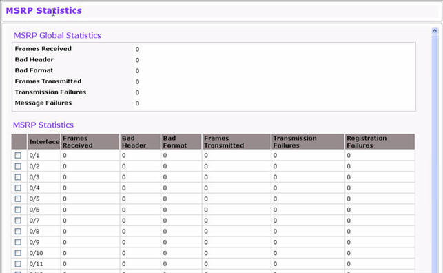
The MSRP Statistics page displays information about the MSRP frames transmitted and received by the switch and by each interface. To access the MSRP Statistics page click Switching > MRP > MSRP Statistics.
MSRP Statistics
Field |
Description |
|
|---|---|---|
Global MSRP Statistics |
||
Frames Received |
Shows number of MSRP frames that have been received on the switch. |
|
Bad Header |
Shows number of MSRP frames with bad headers that have been received on the switch. |
|
Bad Format |
Shows number of MSRP frames with bad PDUs body formats that have been received on the switch. |
|
Frames Transmitted |
Shows number of MSRP frames which that have been transmitted on the switch. |
|
Transmission Failures |
Shows number of MSRP frames the switch failed to transmit. |
|
Message Failures |
Shows the number of messages that failed to be added to the queue. |
|
Per-Interface MSRP Statistics |
||
Interface |
Identifies the interface associated with the rest of the MSRP statistics in the row. |
|
Frames Received |
Displays the number of MSRP frames which were received the interface. |
|
Bad Header |
Displays the number of MSRP frames with bad header which were received on the interface. |
|
Bad Format |
Displays the number of MSRP frames with bad PDUs body format which were received on the interface. |
|
Frames Transmitted |
Displays the number of MSRP frames which were transmitted on the interface. |
|
Transmission Failures |
Displays the number of MSRP frames that an interface attempted to transmit but failed. |
|
Registration Failures |
Shows the number of MSRP frames that failed to register on a device or particular interface. |
|
To reload the page, click Refresh. To clear the statistics for one or more ports, select the check box next to the interface or interfaces, and click Clear. To clear the statistics for all interfaces, select the check box in the heading row, and click Clear Counters.
The MVRP Statistics page displays information about the MVRP frames transmitted and received by the switch and by each interface. To access the MSRP Statistics page click Switching > MRP > MVRP Statistics.
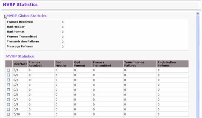
MVRP Statistics
Field |
Description |
|
|---|---|---|
Global MVRP Statistics |
||
Frames Received |
Shows number of MVRP frames that have been received on the switch. |
|
Bad Header |
Shows number of MVRP frames with bad headers that have been received on the switch. |
|
Bad Format |
Shows number of MVRP frames with bad PDUs body formats that have been received on the switch. |
|
Frames Transmitted |
Shows number of MVRP frames which that have been transmitted on the switch. |
|
Transmission Failures |
Shows number of MVRP frames the switch failed to transmit. |
|
Message Failures |
Shows the number of messages that failed to be added to the queue. |
|
Per-Interface MVRP Statistics |
||
Interface |
Identifies the interface associated with the rest of the MVRP statistics in the row. |
|
Frames Received |
Displays the number of MVRP frames which were received the interface. |
|
Bad Header |
Displays the number of MVRP frames with bad header which were received on the interface. |
|
Bad Format |
Displays the number of MVRP frames with bad PDUs body format which were received on the interface. |
|
Frames Transmitted |
Displays the number of MVRP frames which were transmitted on the interface. |
|
Transmission Failures |
Displays the number of MVRP frames that an interface attempted to transmit but failed. |
|
Registration Failures |
Shows the number of MVRP frames that failed to register on a device or particular interface. |
|
To reload the page, click Refresh. To clear the statistics for one or more ports, select the check box next to the interface or interfaces, and click Clear. To clear the statistics for all interfaces, select the check box in the heading row, and click Clear Counters.
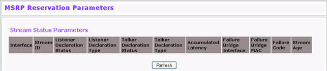
Use the MSRP Reservation Parameters page to view information about the talker, listener, and intermediate device status for the devices involved in each MSRP stream flowing through the switch.
To display the MSRP Reservation Parameters page, click the Switching tab, then click MRP > Advanced > MSRP Reservation Parameters.
MSRP Reservation Parameters Fields
Field |
Description |
|---|---|
Interface |
Identifies the interface associated with the rest of the information in the row. |
Stream ID |
A 16-bit unsigned integer value, Unique ID, used to distinguish among multiple streams sourced by the same system. |
Listener Declaration Status |
Identifies the MSRP declaration status of the listener attribute. |
Listener Declaration Type |
Identifies the MSRP declaration type of the listener attribute. |
Talker Declaration Status |
Identifies the MSRP declaration status of the talker attribute. |
Accumulated Latency |
Identifies how much latency, in nanoseconds, the stream has suffered in its path from the Talker to a given Listener. It starts as a 0 in a Talker Advertise Declaration at the Talker, and its value is increased by one for each bridge as the Talker Advertise Declaration propagates through the network. |
Failure Bridge Interface |
Identifies the interface on the Bridge where the failure occurred. |
Failure Code |
Shows the number that represents the reason for the failure. The switch supports the following codes:
|
Failure Bridge MAC |
Identifies the MAC address of the switch where the failure occurred. |
Stream Age |
The time, in seconds, since the stream destination address was added to the Dynamic Reservations Entries table. A value of zero indicates the destination address has not been added to the table. |
Use the Qav Parameters page to configure and view the per-port IEEE 802.1Qav settings. The IEEE 802.1Qav standard supports time-sensitive traffic streams by pacing all switch traffic, including legacy asynchronous Ethernet traffic, through queuing and forwarding. When a Talker declares a stream, it identifies whether the stream is Class A or Class B and specifies the stream’s bandwidth requirements. Class A traffic has a higher transmission priority than Class B traffic.
On the Qav Parameters page, you can view and configure selected bandwidth allocations for Class A and Class B traffic. To display the Qav Statistics page click Switching > MRP > Qav Parameters.
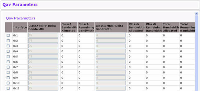
To configure Qav parameters, select the check box next to the port to configure and edit the fields as desired. You can select multiple ports to apply the same settings to the selected interfaces.
Qav Parameter Fields
Field |
Description |
|---|---|
Interface |
Identifies the interface associated with the rest of the data in the row. |
Class A MSRP delta bandwidth |
Class A Delta bandwidth is the additional bandwidth represented as a percentage of port transmit rate which can be reserved for the traffic class A and traffic class B. Class A traffic has a higher priority. |
Class A Bandwidth Allocated |
Shows the current rate of the class A traffic on interface (in Bps). |
Class A Remaining Bandwidth |
Shows the maximum rate of the class A traffic available on interface (in Bps). |
Class B MSRP delta bandwidth |
Class B Delta bandwidth is the additional bandwidth represented as a percentage of port transmit rate which can be reserved for the traffic class B. The range is 0–100. |
Class B Bandwidth Allocated |
Shows the current rate of the class B traffic on interface (in Bps). |
Class B Remaining Bandwidth |
Shows the maximum rate of the class B traffic available on interface (in Bps). |
Total Bandwidth Allocated |
Sum of the allocated Class A and Class B traffic rates on interface (in Bps). |
Total Remaining Bandwidth |
This value is 75% of the interface speed minus total allocated bandwidth (in Bps/sec). |
Use the MSRP Stream Information page to view information about MSRP streams flowing through each interface. To display the MSRP Stream Information page click Switching > MRP > MSRP Stream Information.
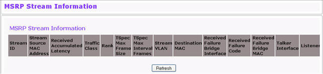
MSRP Streams Information Fields
Field |
Description |
|---|---|
Stream ID |
A 16-bit unsigned integer value, Unique ID, used to distinguish among multiple streams sourced by the same system. |
Stream Source MAC Address |
Identifies the MAC address of the traffic stream’s source. |
Received Accumulated Latency |
The 32-bit unsigned Accumulated Latency component is used to determine the worst-case latency that a Stream can suffer in its path from the Talker to a given Listener. It starts as a 0 in a Talker Advertise Declaration at the Talker, and its value is increased by each Bridge as the Talker Advertise Declaration propagates through the network. |
Traffic Class |
Identifies whether the stream is Class A or Class B. Class A traffic has a higher priority than Class B traffic. |
Rank |
The 5-bit unsigned Rank component is used by systems to decide which streams can and cannot be served, when the MSRP registrations exceed the capacity of a Port to carry the corresponding data streams. If a Bridge becomes oversubscribed the Rank will also be used to help determine which Stream or Streams can be dropped. A lower numeric value is more important than a higher numeric value. |
TSpec Max Frame Size |
The 32-bit unsigned Bandwidth component is used to allocate resources and adjust queue selection parameters in order to supply the quality of service requested by an MSRP Talker Declaration. It represents the maximum rate, in units of 1024 octets per second, at which frames in the Stream referenced by the Talker Declaration may be transmitted. |
TSpec Max Interval Frames |
The 32-bit unsigned Frame Rate component is used to allocate resources and adjust queue selection parameters in order to supply the quality of service requested by an MSRP Talker Declaration. It represents the maximum number of frames that the Talker may transmit in one second. |
Stream VLAN |
Identifies the VLAN ID of the traffic stream. |
Destination MAC |
Identifies the MAC address of the traffic stream’s destination. |
Received Failure Bridge Interface |
Identifies the interface on the Bridge where the failure occurred. |
Received Failure Code |
Identifies the code value of the failure. |
Received Failure Bridge MAC |
Identifies the MAC address of the switch where the failure occurred. |
Talker Interface |
Identifies the interface on which the Talker is present. |
Listeners |
Identifies the interface on which Listeners are present. |